PLL (phase-locked loop) locking state detection circuit

A technology of locked state and detection circuit, applied in the direction of electrical components, automatic power control, etc., can solve the problems of holding, not taking into account the locking signal, unable to identify the phase loss of lock, etc., to achieve the effect of simple circuit structure

Active Publication Date: 2015-04-01
NO 771 INST OF NO 9 RES INST CHINA AEROSPACE SCI & TECH
View PDF6 Cites 22 Cited by
  • Summary
  • Abstract
  • Description
  • Claims
  • Application Information

AI Technical Summary

Problems solved by technology

In order to judge whether the phase-locked loop is locked, some designers use the counter timing method. When the counter timing is greater than the phase-locked loop locking time, it is considered that the phase-locked loop is locked; , so when the phase-locked loop works in different environments, its locking time is different. This method cannot monitor the working status of the phase-locked loop in real time, and can only use the maximum locking time of the pha...

Method used


Image

  • PLL (phase-locked loop) locking state detection circuit
  • PLL (phase-locked loop) locking state detection circuit
  • PLL (phase-locked loop) locking state detection circuit

Examples


Embodiment Construction

[0021] The present invention will be further described in detail below in conjunction with specific embodiments, which are for explanation rather than limitation of the present invention.

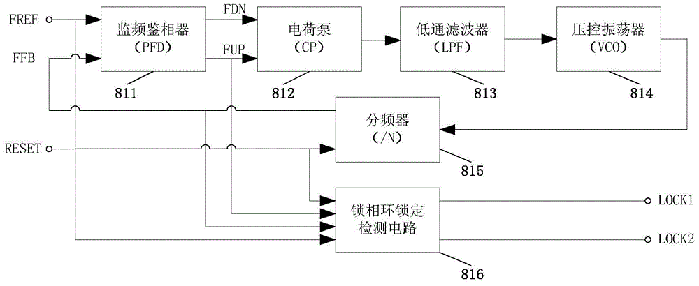
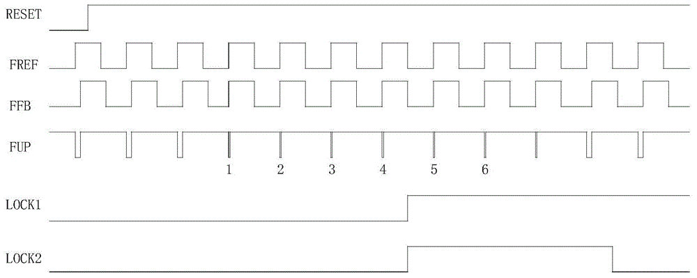
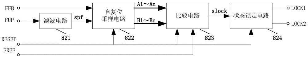
[0022] The present invention is a phase-locked loop locked state detection circuit, such as image 3 As shown, it includes a filter circuit 821, a self-reset sampling circuit 822, a comparison circuit 823, and a state lock circuit 824. And the corresponding relationship of each input signal is as follows figure 2 Shown.

[0023] Before the phase-locked loop lock state detection circuit works, the reset signal should be used to reset the circuit. See Figure 4 , The reset signal RESET is used to reset the phase-locked loop lock state detection circuit, when the RESET signal is low, the flip-flops DFFA1, DFFA2..., DFFAn, DFFAn+1, DFFB1, DFFB2..., DFFBn, DFFBn+1 The data output terminal Q of the comparison flip-flop DFF1 outputs a low level and is in a reset state; the data output terminal Q of ...


PUM


Abstract

The invention provides a PLL (phase-locked loop) locking state detection circuit structure, comprising a filtering circuit, a self-resetting sampling circuit, a comparison circuit and a state locking circuit, wherein the value of a trigger chain level number n of the self-resetting sampling circuit is determined according to specific PLL design indexes; the clock input ends of two trigger chains of the self-resetting sampling circuit are respectively controlled by a PLL feedback frequency and a frequency-monitoring phase discriminator output frequency, so that the judgment on the PLL input reference frequency and feedback frequency state is realized, meanwhile the determined output signal is connected with the input end of the comparison circuit, and the determination and sampling on the determination result are realized by utilization of the comparison circuit; the state locking circuit generates two types of locking signals consisting of a variable state locking signal and a constant state locking signal according to the output signal of the comparison circuit; the detection on the PLL locking state is finished. According to the PLL locking state detection circuit structure, the circuit structure is simple and flexible, and two types of locking signals consisting of the variable locking signal and the constant locking signal can be output according to different application requirements.

Description

Technical field [0001] The invention relates to the field of semiconductor integrated circuits, in particular to a phase-locked loop locked state detection circuit. Background technique [0002] The phase-locked loop uses the principle of feedback control to synchronize the frequency and phase of the input signal and the output signal. It mainly includes five parts: a frequency monitoring phase detector, a charge pump, a low-pass filter, a voltage-controlled oscillator and a frequency divider. Phase-locked loops are widely used in various technical fields such as communications, radar, aerospace, automotive electronics, and measuring instruments. The main function is to generate a stable and reliable high-frequency clock signal. With the rapid development of integrated circuit design technology, the main frequency of circuit work has risen linearly. Therefore, the application range of the phase-locked loop will become wider and wider. [0003] The working state of the phase-locke...

Claims


Application Information

Patent Timeline
IPC IPC(8): H03L7/085
Inventor 李海松高利军尹飞赵德益岳红菊包谦周凤唐威吴龙胜
Owner NO 771 INST OF NO 9 RES INST CHINA AEROSPACE SCI & TECH
Why Eureka
Try Eureka