Automatic gas shielded welding device of longitudinal gap in steel pipe cavity

A technology of gas shielded welding and internal longitudinal seam, which is applied in the direction of auxiliary equipment, welding equipment, welding equipment, etc., can solve the problems of difficult to guarantee weld quality, low production efficiency, welder injury, etc., and achieve improved welding efficiency, convenient operation, The effect of avoiding harm to persons

Inactive Publication Date: 2015-04-08
河北省景县宏远通讯有限公司
View PDF8 Cites 20 Cited by
  • Summary
  • Abstract
  • Description
  • Claims
  • Application Information

AI Technical Summary

Problems solved by technology

[0002] At present, the iron tower industry generally adopts the welding process of single-sided welding and double-sided forming for the longitudinal seam welding of steel pipe rods. When the thickness of the steel plate is thick, it is difficult to guarantee the internal quality of the weld and the production efficiency is low.
If internal and external welding is adopted, large-diameter steel pipes (when the diameter is greater than or equal to 600mm) need to be welded by the welder into the interior of the steel pipe, and the harmful gas generated during the welding process will easily hurt the welder
And the diameter of the steel pipe is different, and the steel pipe with a smaller diameter (diameter less than 600mm) welders cannot enter the inside of the steel pipe for welding

Method used


Image

  • Automatic gas shielded welding device of longitudinal gap in steel pipe cavity
  • Automatic gas shielded welding device of longitudinal gap in steel pipe cavity
  • Automatic gas shielded welding device of longitudinal gap in steel pipe cavity

Examples


Embodiment Construction

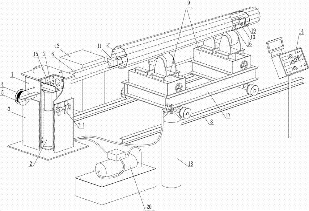
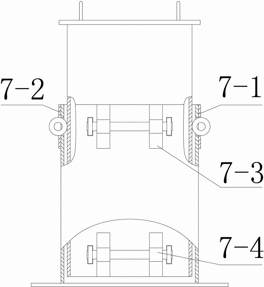
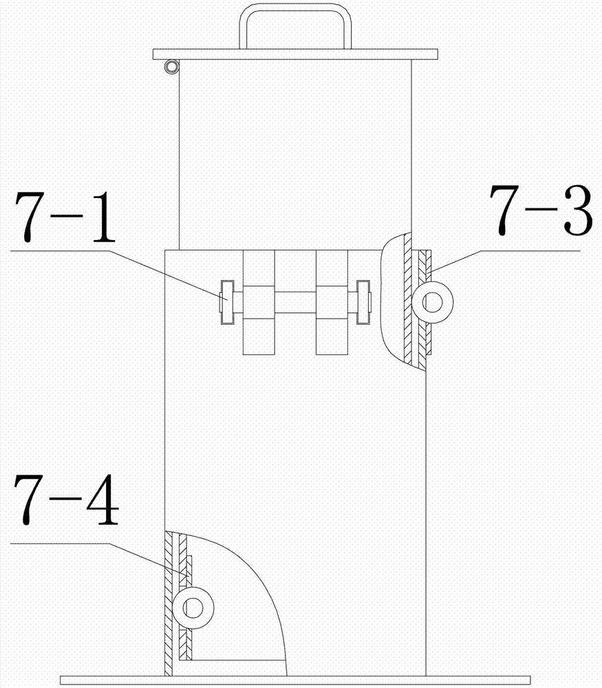
[0023] as attached figure 1 Shown, the present invention comprises machine head, support arm 6, running gear, welder 13, welding torch 10, control box 14, support wheel frame 19; Described machine head is a box type, and it comprises outer machine head 3 and is arranged on The inner machine head 1 in the head 3 is provided with a lifting cylinder 2 inside the outer machine head 3, and the lifting oil cylinder 2 is connected with the oil pump 20 arranged on the outside of the outer machine head 3 through an oil pipe, and is fixedly installed in the inner machine head 1 Support beam 12; as attached figure 1 , 2 , 3, the present invention sets the lifting guide wheel A 7-1, the lifting guide wheel B 7-2 and the lifting guide wheel C 7-3 on the outer upper part of the outer machine head 3 respectively, and the lifting guide wheel A 7- 1. The guide wheels on the lifting guide wheel B 7-2 and the lifting guide wheel C 7-3 pass through the side wall of the outer machine head 3 and ...


PUM


Abstract

The invention relates to an automatic gas shielded welding device of a longitudinal gap in a steel pipe cavity. The device comprises a machine head, a support arm, a walking device, a welding machine, a welding gun, a control box and a support wheel frame, wherein the machine head consists of an outer machine head and an inner machine head; one end of the support arm is fixed at the other side of the inner machine head; the support wheel frame is fixed at the other end of the support arm; an oscillator and a fixture fixed at one side of the oscillator are fixed in the support wheel frame; the welding gun is fixed in the middle of the fixture; a welding gun observing probe is fixed below the end of the support arm; and an automatic wire feeding machine is fixed in a mounting groove hole in the support arm. The device is simple in structure and convenient for operation, can largely improve the welding efficiency and reduce the labor intensity, needs no welding workers to enter steel pipes for welding to prevent harmful gas from harming the workers, and improves the product quality.

Description

technical field [0001] The invention relates to an automatic gas shielded welding device for longitudinal seams in a steel pipe cavity. Background technique [0002] At present, the iron tower industry generally adopts the welding process of single-sided welding and double-sided forming for the longitudinal seam welding of steel pipe rods. When the thickness of the steel plate is thick, it is difficult to guarantee the internal quality of the weld and the production efficiency is low. If internal and external welding is adopted, large-diameter steel pipes (when the diameter is greater than or equal to 600mm) need to be welded by welders entering the interior of the steel pipe, and the harmful gas generated during the welding process is likely to cause injury to the welder. And the diameters of steel pipes are different, and the welders of steel pipes with smaller diameters (diameter less than 600mm) cannot enter the interior of the steel pipes for welding. Contents of the ...

Claims


Application Information

Patent Timeline
Patent Type & Authority Applications(China)
IPC IPC(8): B23K9/16B23K9/025B23K9/12B23K9/32B23K9/127B23K37/053B23K101/06
CPCB23K9/0253B23K9/12B23K9/127B23K9/16B23K9/32B23K37/0533B23K2101/06
Inventor 范洪章孙季德李计学范晓光李俊良韩忠礼郑文攀王丽德王超超张端华范志勇
Owner 河北省景县宏远通讯有限公司
Why Eureka
Try Eureka