Heat-conducting oil boiler waste heat power generation system

A heat-conducting oil boiler and waste heat power generation technology, which is applied to steam boilers, heat storage heaters, steam generation methods using heat carriers, etc., can solve the problem that the waste heat of heat-conducting oil boiler flue gas has not been fully recovered and utilized, and achieve improved fuel efficiency. Combustion efficiency, improving waste heat recovery rate, and improving the effect of waste heat recovery utilization rate

Inactive Publication Date: 2015-04-08
陈翔
View PDF8 Cites 2 Cited by
  • Summary
  • Abstract
  • Description
  • Claims
  • Application Information

AI Technical Summary

Problems solved by technology

However, this flue gas waste heat recovery power generation device only uses the high-temperature flue gas from the heat-conducting oil boiler to heat the cold water into high-temperature water, and then directly discharges the high-temperature flue gas into the atmosphere. The power generation system also needs an additional waste heat boiler to heat the warm water into steam for the steam turbine to generate electricity

Method used


Image

  • Heat-conducting oil boiler waste heat power generation system

Examples


Embodiment approach

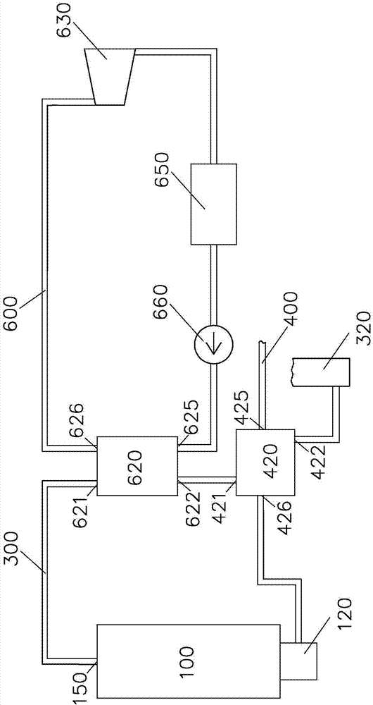
[0023] Please refer to figure 1 , according to an embodiment of the present invention, the thermal oil boiler waste heat power generation system includes: a furnace body 100, a nozzle 120, a flue gas pipeline 300, a chimney 320, an air pipeline 400, an air preheater 420, a water vapor cycle power generation circuit 600, Steam generator 620 , steam turbine 630 , screw generator 650 and water pump 660 .

[0024] The furnace body 100 is provided with a furnace (not shown) for heating the heat transfer oil. The nozzle 120 is arranged on one end wall of the furnace body 100, and is used for injecting fuel and combustion-supporting air into the furnace for burning and releasing heat.

[0025] The flue gas pipe 300 is connected to the other end wall of the furnace body 100 for discharging the flue gas from the furnace body flue gas outlet 150 to the chimney 320 .

[0026] The air pipeline 400 is connected to the nozzle 120, and is used for delivering the combustion air to the nozzl...


PUM


Abstract

The invention discloses a heat-conducting oil boiler waste heat power generation system. The heat-conducting oil boiler waste heat power generation system comprises a furnace body, a spray nozzle, a flue gas pipe and an air pipe, wherein a furnace hearth for heating heat-conducting oil is arranged inside the furnace body; the spray nozzle is arranged in the end wall of one side of the furnace body and is used for spraying fuel and combustion air into the furnace hearth for combusting and releasing heat; the flue gas pipe is connected to the end wall of the other side of the furnace body and is used for discharging flue gas from a flue gas outlet of the furnace body to a chimney; the air pipe is connected to the spray nozzle and is used for conveying the combustion air to the spray nozzle; the heat-conducting oil boiler waste heat power generation system further comprises a water steam circulating power generation circuit; the water steam circulating power generation circuit comprises a steam generator arranged inside the flue gas pipe, and a steam turbine connected with the steam generator through a pipeline.

Description

technical field [0001] The invention relates to a waste heat power generation system, in particular to a boiler flue gas waste heat power generation system. Background technique [0002] In the face of increasingly severe environmental problems and energy crises, the whole world is vigorously advocating energy conservation and emission reduction, especially for industrial kiln related industries with serious energy consumption and pollution. Factors that personnel must consider when designing such equipment. [0003] Taking the heat transfer oil boiler as an example, the flue gas temperature at the flue gas outlet usually reaches about 400 degrees Celsius. If these high-temperature flue gases are directly discharged into the environment, it will not only cause energy waste but also cause a certain degree of damage to the environment. [0004] For example, China Patent No. 200820139475.9 discloses a flue gas waste heat recovery power generation device, which is composed of ...

Claims


Application Information

Patent Timeline
Patent Type & Authority Applications(China)
IPC IPC(8): F23J15/06F23L15/00F22B1/16F22B31/08F24H7/02F01K7/00
CPCY02E20/34
Inventor 陈翔
Owner 陈翔
Why Eureka
Try Eureka