
Inversion method utilizing single hydrophone to measure reverberation time of non-anechoic pool

A non-anechoic pool and reverberation time technology, which is applied in the measurement of reverberation time, ultrasonic/sonic/infrasonic waves, measurement devices, etc., can solve the difficulty of measuring reverberation time in non-anechoic pools, High wall absorption characteristics, large characteristic impedance, and no measurement of reverberation time, etc., to achieve the effects of high test efficiency, easy operation and accurate results

Active Publication Date: 2015-04-08
HARBIN ENG UNIV
View PDF3 Cites 19 Cited by
  • Summary
  • Abstract
  • Description
  • Claims
  • Application Information

AI Technical Summary

Problems solved by technology

[0003] The measurement specification in air ISO 3382-1997 gives the method of measuring the reverberation time of the air reverberation chamber by the impulse response method and the steady-state noise interruption method, but due to the high absorption characteristics of the non-anechoic pool wall and the huge characteristic impedance of water And factors such as the interference effect of the boundary on the sound field make it difficult to measure the reverberation time of the non-anechoic pool.
At present, there is no report on the calculation of reverberation time by measuring the spatially averaged sound pressure level inversion of known sound sources in a non-anechoic pool, and there is no specific report on the measurement of reverberation time in a narrow-band frequency range.

Method used


Image

  • Inversion method utilizing single hydrophone to measure reverberation time of non-anechoic pool
  • Inversion method utilizing single hydrophone to measure reverberation time of non-anechoic pool
  • Inversion method utilizing single hydrophone to measure reverberation time of non-anechoic pool

Examples

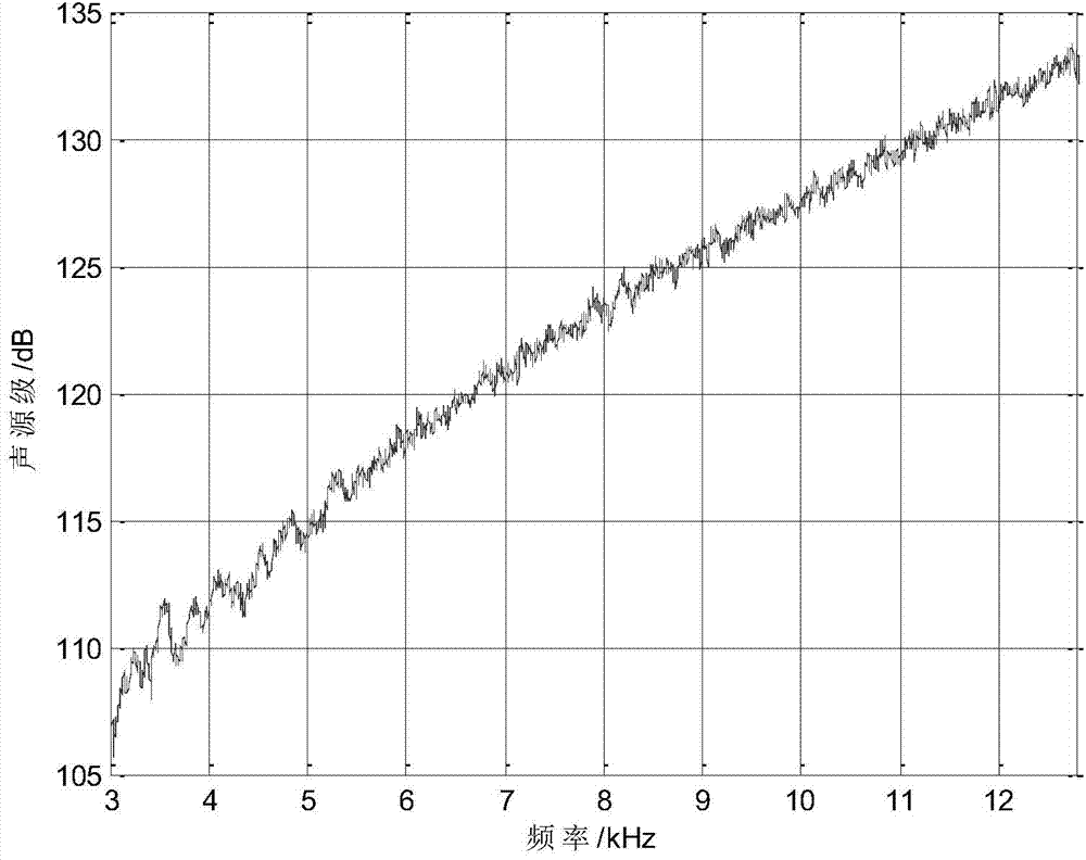

Embodiment Construction

[0025] The present invention will be further described below in conjunction with the accompanying drawings.

[0026] The method of the present invention comprises the following steps:

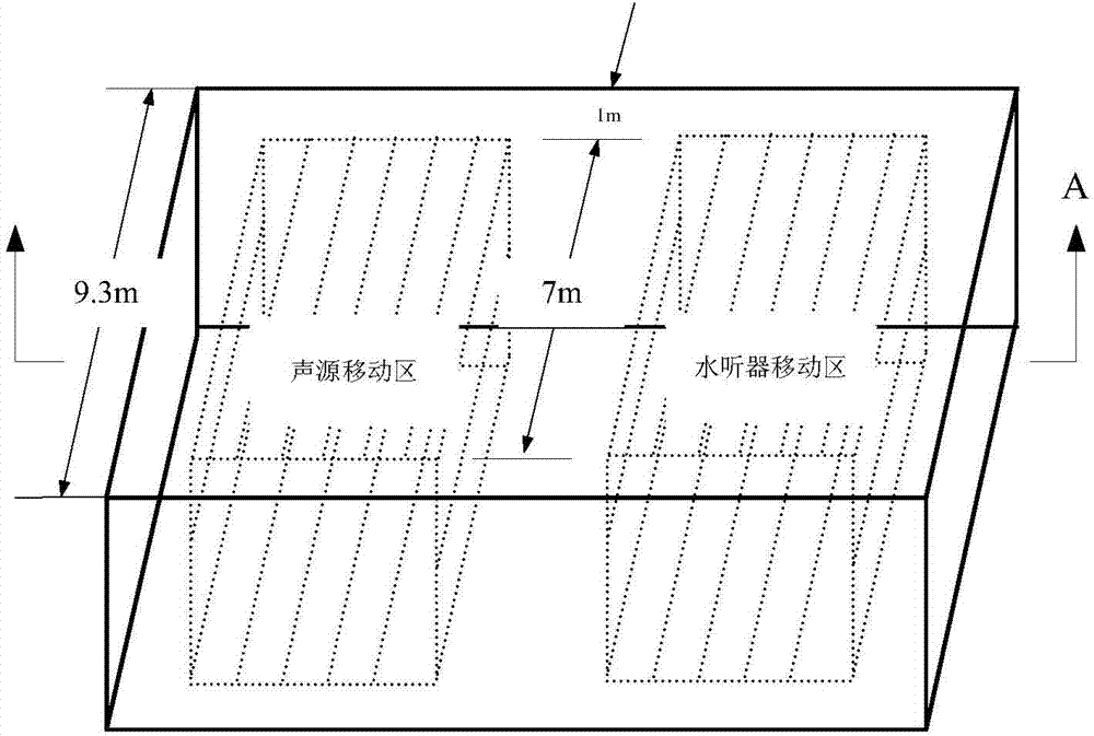
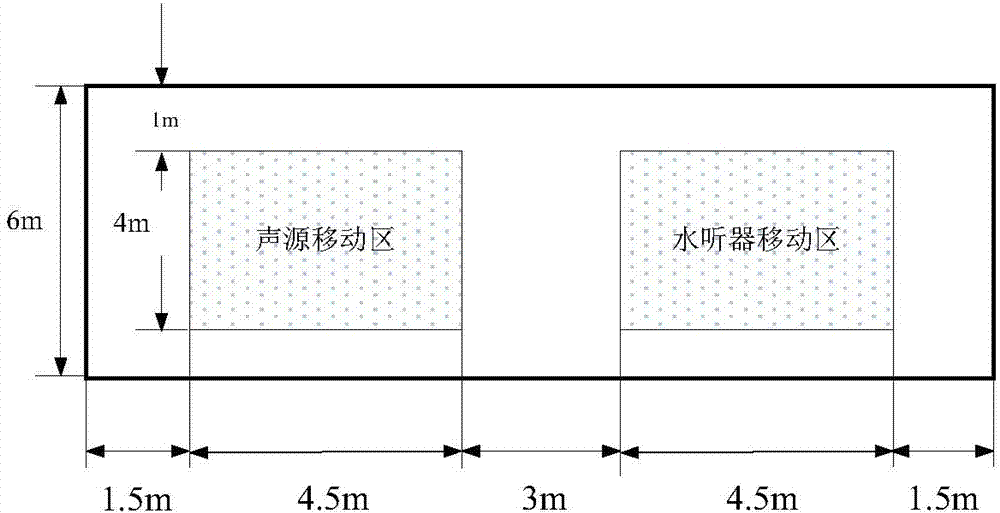
[0027] (1) Measure the sound source level of an omnidirectional sound source in an anechoic pool (or open water). Place the omnidirectional sound source to be tested and a calibrated hydrophone in the middle of the anechoic pool. The sound centers of the two are at the same depth and the horizontal distance satisfies the far-field test conditions. In the frequency range above the lower limit of the anechoic frequency of the anechoic pool, wide-band random white noise is used as the excitation input of the non-directional sound source, and the signal input amplitude is adjusted to meet the SNR requirements of the measurement. The sound pressure amplitude, and record the frequency loaded on the sound source, the voltage amplitude, the horizontal distance between the sound source and the sound ce...


PUM


Abstract

The invention relates to a reverberation time measurement method and particularly relates to an inversion method utilizing a single hydrophone to measure reverberation time of a non-anechoic pool. The method comprises steps that, a sound source level of a random non-directional sound source is measured in an anechoic pool by utilizing a calibrated hydrophone and is recorded and loaded to frequency and voltage amplitude on the sound source; the non-directional sound source and the hydrophone are put to a to-be-measured non-anechoic pool, frequency and voltage amplitude are recorded and are loaded to the non-directional sound source, the sound source and the hydrophone are simultaneously and slowly moved, and an average space sound pressure level is acquired by utilizing the hydrophone for measurement; the reverberation time of the non-anechoic pool can be acquired through inversion calculation according to the sound source level of the non-directional sound source in a free field and the measured average space sound pressure level of the sound source in the to-be-measured non-anechoic pool. The method has properties of high test efficiency and accurate result, and the average sound energy density attenuation time can be measured not on the basis of definition of the reverberation time.

Description

technical field [0001] The invention relates to a method for measuring the reverberation time, in particular to an inversion method for measuring the reverberation time of a non-anechoic pool by using a single hydrophone. Background technique [0002] Reverberation time is an important attribute of non-anechoic pools, and an important calculation parameter for acoustic measurement under reverberation conditions using non-anechoic pools. The main applications of acoustic measurement in non-anechoic pools using reverberation time include: measurement of the absorption coefficient of materials, measurement of the absorption characteristics of sediment, and measurement of radiated sound power of sound sources. The traditional methods of measuring reverberation time in non-anechoic pools are all based on the specifications for measuring reverberation time in reverberation chambers in the air, and are generally realized through the measurement of a collector with a reverberation t...

Claims


Application Information

Patent Timeline
IPC IPC(8): G01H7/00
Inventor 李琪唐锐尚大晶刘永伟
Owner HARBIN ENG UNIV
Learn More