Plane multi-port power divider

A multi-port, power divider technology, used in waveguide-type devices, electrical components, connecting devices, etc., can solve the increasing influence of processing error indicators, increasing the equivalent input impedance of the power divider, and increasing design difficulties, etc. problem, to achieve the effect of easy processing, strong superiority and small size

Inactive Publication Date: 2015-04-08
XIDIAN UNIV
View PDF0 Cites 12 Cited by
  • Summary
  • Abstract
  • Description
  • Claims
  • Application Information

AI Technical Summary

Problems solved by technology

When this scheme has a large number of ports (generally N≥3), it becomes very difficult to add resistance between the two branches
At the same time, with the increase of N, the characteristic impedance of N parallel branches will increase, resulting in thinner and thinner microstrip lines, and the influence of processing errors on indicators will become greater and greater.
Therefore, the number of output ports N of this scheme is limited to a certain extent.
[0005] The latter is the scheme proposed in the literature [2] (Sushim Mukul Roy, Isaac Balbin, and Nemai Chandra Karmakar, Novel N-way Power Divider and Array Configuration for RFID, 2008IEEE Int RFID, 2008, 89-96.), namely After the energy is fed from the input port, it passes through a large disk, which is in a low-resistance state, and then N branches are directly added to the outside of the disk to achieve N-way output. This type of power divider has poor isolation (not added In addition to the isolation resistance), since the size of the disk determines its characteristic impedance and equivalent electrical length, in order to obtain an ideal matching effect, the selection of the number of N is often subject to certain restrictions, so it is necessary to increase the power divider as a whole The size or the equivalent input impedance of the output port changes, making the design more difficult

Method used


Image

  • Plane multi-port power divider
  • Plane multi-port power divider
  • Plane multi-port power divider

Examples


Embodiment Construction

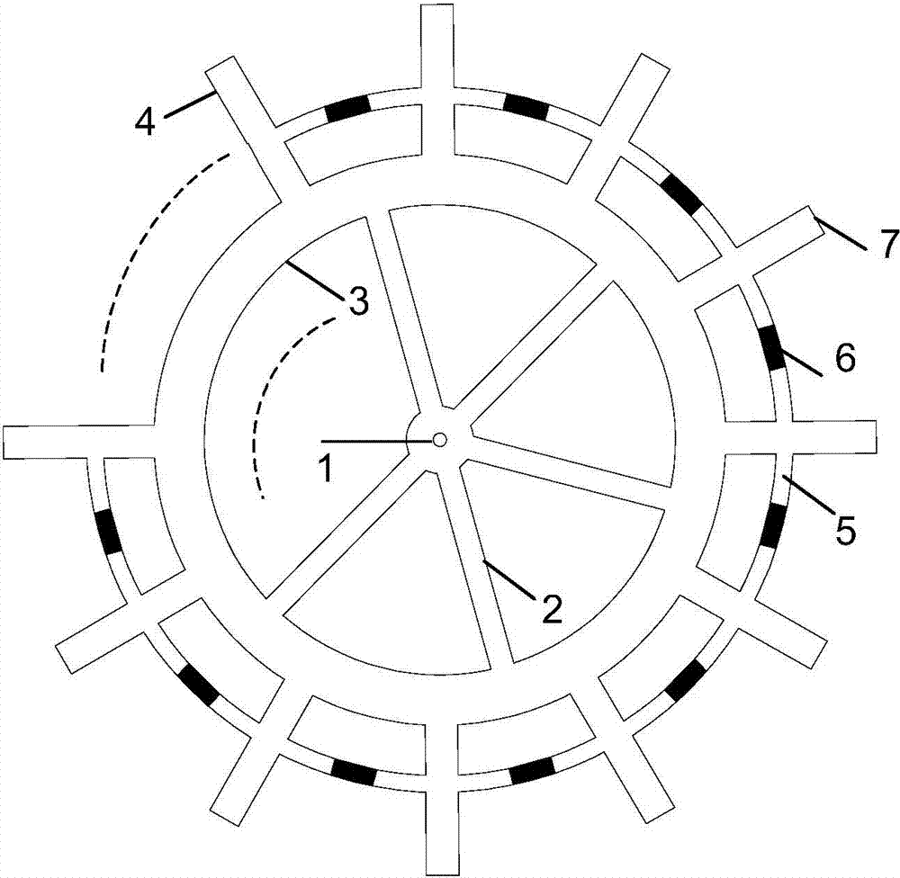
[0025] The present invention will be described in further detail below in conjunction with the accompanying drawings.

[0026] see figure 1 , the present invention includes several radio frequency transmission lines composed of metal strip lines and metal plates, wherein the metal strip line includes a total input port 1 and N output ports 7, N≥3; the total input port 1 and N output ports 7 There is an annular stripline 3 for impedance matching, the total input port 1 is connected to the annular stripline 3 through M parallel branch striplines 2, M≥1, and the annular stripline 3 is connected respectively through N output branch striplines 4 N output ports 7; among the output stub strip lines 4, at least two of the strip lines are provided with a resistor 6, and the resistor 6 is connected to the two output stub strip lines 4 through the resistance connecting strip line 5.

[0027] The planar multi-port power divider of the present invention can be realized by a microstrip lin...


PUM


Abstract

The invention discloses a plane multi-port power divider which comprises a plurality of radio frequency transmission lines consisting of metal strip lines and metal plates. Each metal strip line comprises a main input port and N output ports, wherein an annular strip line used for impedance matching is arranged between the main input port and the N output ports; the main input port is connected with the annular strip line by M parallel branch strip lines; the annular strip line is connected with the N output ports by N output branch strip lines; resistors are arranged between at least two of the output branch strip lines; and each resistor is connected with the two output branch strip lines by resistor connecting strip lines; M is greater than or equal to 3 and N is greater than or equal to 1. The power divider has the characteristics of small size and high isolation; the insertion loss of the power divider can be reduced by size reduction; the isolation between array unit channels can be improved by improving the isolation of the output ports of the power divider, so that the influence of mutual coupling between antenna array units is reduced, and the radiation performance is improved; and in addition, the power divider is in a pure plane structure, is easy to process and excellent in engineering practical value.

Description

technical field [0001] The invention relates to a radio frequency passive device, in particular to a planar multi-port power divider. Background technique [0002] A power splitter, as the name implies, distributes the power of an input port to multiple output ports. The power splitter can be widely used as a feed network in the field of array antennas. Existing power splitters include T-shaped branches or Wilkinson and other forms. The T-shaped stub power divider is simple in design and small in size, but its port isolation is poor; the Wilkinson power divider solves the problem of poor port isolation by connecting a resistor between two output channels, but it is often The layout flexibility is not as good as the T-shaped branch scheme. [0003] For an array antenna with Y number of array elements, there are mainly two implementation schemes for its power division feed network. The first scheme uses multiple 1-divider X power dividers cascaded (X<Y), for example, a 4...

Claims


Application Information

Patent Timeline
Patent Type & Authority Applications(China)
IPC IPC(8): H01P5/16
Inventor 樊芳芳鄢泽洪王金辉雷娟张天龄
Owner XIDIAN UNIV
Why Eureka
Try Eureka