
Eureka
For R&D, Eureka makes reading and utilizing patents & technical documents easy.
Eureka AIR
Designed for self-driven R&D workflows. Generate viable solutions, solve complex R&D challenges, empower your innovation with AI.

Eureka Materials
Designed for material experts only. Revolutionize your material R&D, from search, analyze, to developing new materials.

TechResearch
Generate reliable direction feasibility study reports for your R&D in just a few steps.

TechSeek
Discover and master advanced knowledge NOW. Basics, ideas, possibilities, all at once.

TechMind
As an expert in R&D Theories, TechMind can generates customized viable solutions instantly.

TechRisk
Analyze your overall solution with one click, know your potential R&D risks in advance.

TechMonitor
Get weekly tech updates, stay abreast of the latest tech innovations and key insights.
Electric working machine
A technology for working machines and electric motors, which is applied to electric components, synchronous motors with stationary armatures and rotating magnets, and electromechanical devices, etc., can solve problems such as waste of energy and friction loss, and achieve the effect of improving energy efficiency and good cooling.
- Summary
- Abstract
- Description
- Claims
- Application Information
AI Technical Summary
Problems solved by technology
Method used
Image

Examples
no. 1 example
[0032] Preferred embodiments of the present invention are described below with reference to the accompanying drawings. Incidentally, the same or equivalent devices, components, steps, etc. shown in the respective drawings are denoted by the same reference numerals, and repeated descriptions are appropriately omitted. In addition, the embodiments are intended to explain the present invention, not to limit the present invention; therefore, all the features and combinations thereof described in the embodiments are not necessarily essential to the present invention.
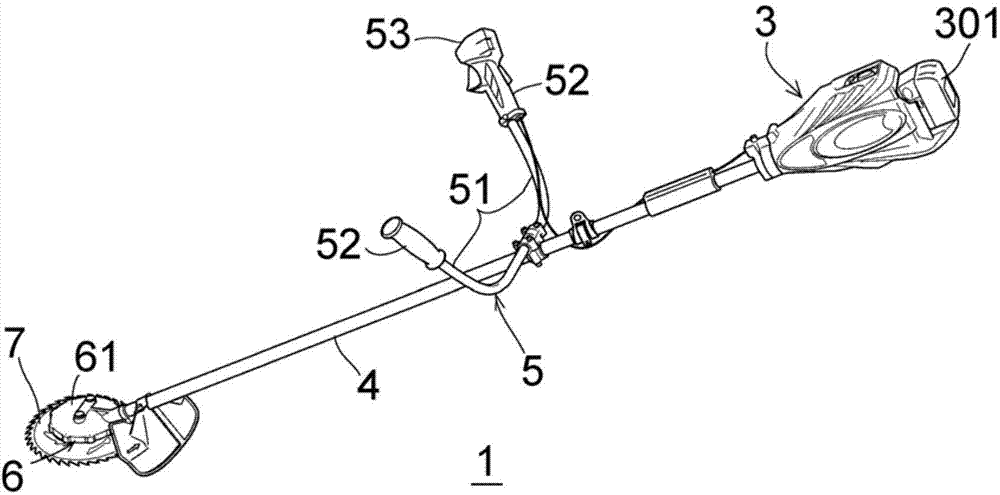
[0033] figure 1 is a perspective view showing an electric brush cutter 1 as an electric working machine according to the first embodiment of the present invention. A brush cutter 1 as an example of an electric working machine includes a power supply unit 3 , a pipe portion 4 , a handle portion 5 , a drive unit 6 and a cutting blade 7 . Cutting work is performed using the cutting blade 7 as a work unit mounted on th...
no. 2 example
[0057] Figure 9 A side sectional view of an electric trimmer 100 according to a second embodiment of the present invention is shown. The electric trimmer 100 includes: a casing 101; a handle portion 102 integrally formed with the casing 101; a brushless disc motor 10 disposed at a lower position inside the casing 101; a blade holding portion 110 fixed to the casing. body; and two blades 111 and 112, which are held on the blade holding portion 110 and can reciprocate.
[0058] The disc motor 10 is the same as the disc motor in the first embodiment in that it also includes the extension 45 of the coil plate 41 . In the second embodiment, the output shaft 31 of the disc motor 10 is rotatably supported by the bearing 120 fixed inside the housing 101 . The rotation of the output shaft 31 is transmitted to the two blades 111 and 112 via the transmission mechanism 121, and the two blades 111 and 112 are used as a working unit, and the transmission mechanism 121 is used to convert ...
no. 3 example
[0064] Figure 10 A side sectional view of an electric trimmer 100A according to a third embodiment of the present invention is shown. In this case, the disc motor 10A does not have an extension provided on the coil plate 41, so the motor drive circuit (inverter circuit or control circuit) is provided as a separate circuit board 140 located on the centrifugal fan 90 in the channel of the fan airflow generated. That is, the circuit board 140 is disposed in an air flow passage entering the centrifugal fan 90 from the air intake hole 130 through an upper opening of the fan guide 91 (eg, an opening formed around the output shaft 31 ). Other configurations are the same as those in the second embodiment.
[0065] In the third embodiment, the circuit board 140 on which the motor drive circuit is mounted can also be effectively cooled by the fan air flow. The disc motor 10A and the circuit board 140 on which the motor driving circuit is mounted are independent from each other, ther...
PUM
 Abstract
Description
Claims
Application Information
 - R&D Engineer
- R&D Manager
- IP Professional
- Industry Leading Data Capabilities
- Powerful AI technology
- Patent DNA Extraction
Browse by: Latest US Patents, China's latest patents, Technical Efficacy Thesaurus, Application Domain, Technology Topic, Popular Technical Reports.
© 2024 PatSnap. All rights reserved.Legal|Privacy policy|Modern Slavery Act Transparency Statement|Sitemap|About US| Contact US: help@patsnap.com