Oil well fracturing flowback fluid recovery sand removal device

A liquid recovery and flowback technology, which is applied in the direction of mining fluid, flushing wellbore, wellbore/well components, etc., can solve the problems of high environmental risk and difficult treatment of flowback fluid, and achieve short settlement time and reduce harmless The effect of processing cost and occupying a small area

Active Publication Date: 2017-11-03
CHINA NAT PETROLEUM CORP CHUANQING DRILLING ENG CO LTD CHANGQING DOWNHOLE TECH CO
View PDF1 Cites 0 Cited by
  • Summary
  • Abstract
  • Description
  • Claims
  • Application Information

AI Technical Summary

Problems solved by technology

[0004] The purpose of the present invention is to provide an oil well fracturing flowback fluid recovery and desanding device to solve the problems in the prior art that a large amount of flowback fluid generated after operation is difficult to handle and the environmental risk is large

Method used


Image

  • Oil well fracturing flowback fluid recovery sand removal device
  • Oil well fracturing flowback fluid recovery sand removal device
  • Oil well fracturing flowback fluid recovery sand removal device

Examples


Embodiment 1

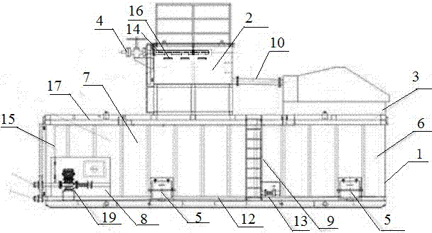
[0019] This embodiment provides an oil well fracturing flowback liquid recovery and desanding device, including a liquid storage tank 1, a buffer tank 2, and a vibrating screen 3. The liquid storage tank 1 is open, and the buffer tank 2 and the vibrating screen 3 are all located in the On the top of the liquid storage tank 1, the side of the buffer tank 2 is provided with a flowback liquid inlet 4, and the buffer tank 2 communicates with the vibrating screen 3 through the communication pipeline 10;

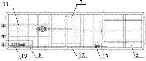
[0020] The liquid storage tank 1 is composed of an isolation area 8, a liquid storage area 7, and a sand settling area 6 arranged horizontally in sequence. 8 is equipped with a centrifugal pump 19, which communicates with the liquid storage area 7 through the pump discharge pipeline, and an overflow plate 9 is provided between the liquid storage area 7 and the sand settling area 6, and the lower part of the liquid storage area 7 and the sand settling area 6 is equipped with The sa...

Embodiment 2

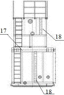
[0023] On the basis of Embodiment 1, the buffer tank 2 is provided with a cleaning pipe 15 connected to the flowback liquid inlet 4, and three strip-shaped through-holes 16 are evenly distributed on the cleaning pipe 15 .

[0024] The fracturing flowback fluid enters the buffer tank 2 through the flowback fluid inlet 4, and the pressure inside the pipe is reduced through the three strip-shaped through holes 16 evenly distributed on the cleaning pipe 15, which facilitates the drainage and sand carrying, and then enters the vibrating screen 3 through the connecting pipeline , the liquid separated in the vibrating screen 3 enters the grit chamber 6, and when the liquid level exceeds the overflow plate 9 after precipitation, the liquid enters the liquid storage area 7 and is discharged through the first liquid discharge line 11. The flowback liquid is recycled; the sand after sedimentation is discharged through the sand cleaning door 5 and can be reused.

Embodiment 3

[0026] On the basis of embodiment 2, the bottom of the liquid storage tank 1 is provided with the second liquid discharge pipeline 12 connecting the isolation area 8, the liquid storage area 7, and the grit chamber 6, and the second liquid discharge line 12 is connected to the liquid storage area 7 and A connecting gate 13 is provided between the grit chambers 6 .

[0027] The fracturing flowback fluid enters the buffer tank 2 through the flowback fluid inlet 4, and the pressure inside the pipe is reduced through the three strip-shaped through holes 16 evenly distributed on the cleaning pipe 15, which facilitates the drainage and sand carrying, and then enters the vibrating screen 3 through the connecting pipeline , the liquid separated in the vibrating screen 3 enters the grit chamber 6, and when the liquid level exceeds the overflow plate 9 after precipitation, the liquid enters the liquid storage area 7 and is discharged through the first liquid discharge line 11. The flowb...


PUM


Abstract

The invention belongs to the technical field of fracturing fluid recovery in the oil-field development process and particularly relates to an oil well fracturing flowback fluid recovering and desanding device. The oil well fracturing flowback fluid recovering and desanding device comprises a fluid storage tank, a buffer tank and a vibrating screen. The fluid storage tank is open. The buffer tank and the vibrating screen are both arranged on the top of the fluid storage tank. One side of the buffer tank is provided with a flowback fluid inlet. The buffer tank is communicated with the vibrating screen through a communicating pipeline. By the adoption of the oil well fracturing flowback fluid recovering and desanding device, flowback fluid can meet the performance requirement for reutilization after being treated and be applied to operation of a next well, so the harmless treatment cost of waste is lowered, t the flowback fluid polllutes the environment is reduced, construction materials are saved, and energy conservation and emission reduction are achieved. The oil well fracturing flowback fluid recovering and desanding device has the advantages that the settling time is short, continuous treatment of the flowback fluid can be achieved, and the occupied area of a settling pond is small, and is a oil well fracturing flowback fluid efficient recovering, separating, metering and storing device.

Description

technical field [0001] The invention belongs to the technical field of fracturing fluid recovery in the oil field development process, and in particular relates to a sand removal device for oil well fracturing flowback fluid recovery. Background technique [0002] As the number of horizontal wells increases in recent years and the scale of reconstruction increases, the amount of fluid used for oil well fracturing and fluid flowback after fracturing increases sharply, resulting in a huge consumption of water resources and a substantial increase in the cost of waste fluid treatment. The traditional non-recyclable Fracking fluids exacerbate the problem. With the deepening of national environmental protection policies and the strengthening of environmental protection departments in oil regions, new challenges have been brought to downhole operations. The rough and violent discharge mode of fracturing working fluid in traditional oil test wells is no longer suitable for the envi...

Claims


Application Information

Patent Timeline
Patent Type & Authority Patents(China)
IPC IPC(8): E21B43/26E21B21/06
CPCE21B43/26
Inventor 白明伟王文渭杜巧珍李启新张小平周真
Owner CHINA NAT PETROLEUM CORP CHUANQING DRILLING ENG CO LTD CHANGQING DOWNHOLE TECH CO
Why Eureka
Try Eureka