
Airport apron pipe network impermeability testing device and method based on pressure correlation method

A testing device and airtightness technology, which is applied in the direction of using liquid/vacuum degree for liquid tightness measurement and measuring the fluid's acceleration and deceleration rate. , feasibility, low accuracy, short distance of the apron pipe network, etc., to achieve the effect of rich display content, simple calculation and high feasibility

Active Publication Date: 2015-04-22
CHINA UNIV OF PETROLEUM (EAST CHINA)
View PDF11 Cites 7 Cited by
  • Summary
  • Abstract
  • Description
  • Claims
  • Application Information

AI Technical Summary

Problems solved by technology

[0008] (1) Due to the short distance of the apron pipeline network and the particularity of the refueling operation, every refueling is an external interference. The above patents do not propose effective interference elimination measures, so it is easy to cause false alarms
[0009] (2) The above patents are all leak detection methods proposed when the pipeline network is in dynamic operation, and have not proposed a better solution to the static airtightness test of the pipeline network
[0010] In short, the above patents are not practical, feasible, and accurate in testing the airtightness of the apron pipe network. Therefore, the present invention proposes a test device and method for the airtightness of the apron pipe network based on the pressure correlation method.

Method used


Image

  • Airport apron pipe network impermeability testing device and method based on pressure correlation method
  • Airport apron pipe network impermeability testing device and method based on pressure correlation method
  • Airport apron pipe network impermeability testing device and method based on pressure correlation method

Examples


Embodiment Construction

[0046] In order to make the purpose and technical solution of the present invention clearer, the present invention will be further described in detail below with reference to the accompanying drawings.

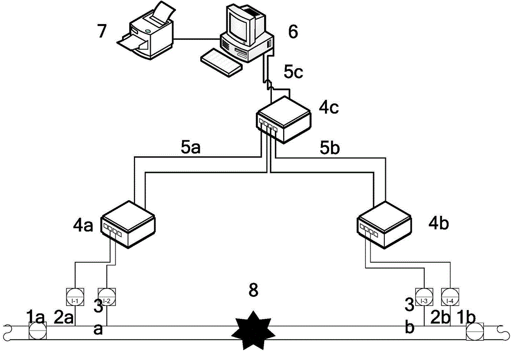
[0047] as attached figure 1 As shown, a test device for the airtightness of the apron pipe network based on the pressure correlation method includes a simulation test component, a transmitter group, a data collector (4a, 4b and 4c), and a data transmission medium (5a, 5b and 5c) and monitoring host 6.

[0048] Precision cut-off valves (1a and 1b) are used to cut off the pipe section to be tested, and form a simulated test assembly with the charging pump, pressure relief valve and leakage valve, and oil recovery device.

[0049] The pressure transmitter 2a and the temperature transmitter 3a form the first transmitter group; the pressure transmitter 2b and the temperature transmitter 3b form the second transmitter group. Install the first set of transmitter sets at the beginni...


PUM


Abstract

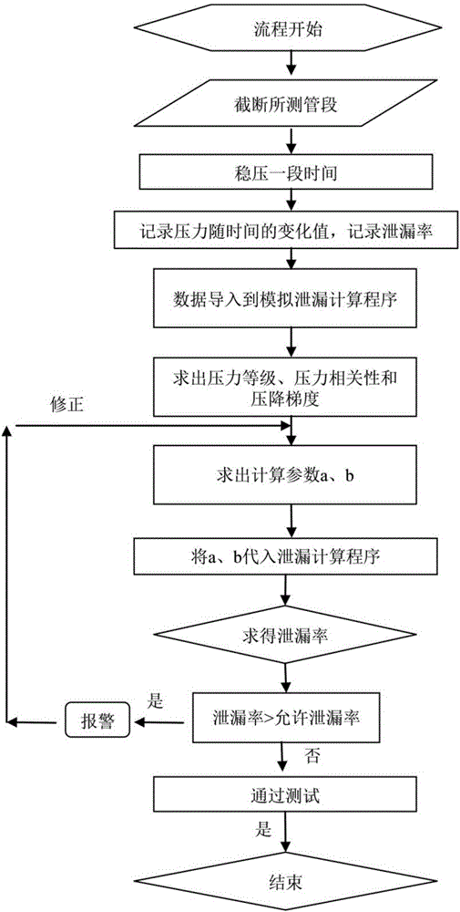
The invention discloses an airport apron pipe network impermeability testing device and method based on a pressure correlation method. The testing device comprises a simulation testing assembly, transmitter sets, data collectors, data transmission media and a monitoring host. The testing method is divided into a leakage simulating testing process and an impermeability testing process, and includes the steps of firstly, carrying out simulation leakage testing on a to-be-tested pipe section, recording a leakage rate, and collecting pressure data and temperature data of the pipe section; secondly, introducing the pressure data into a leakage simulation calculating program to obtain the pressure drop gradient in the corresponding pressure grade, and then obtaining a calculation parameter; then starting the impermeability testing program to re-collect the pressure data and the temperature data of the pipe section, carrying out sealing performance testing on the pipe section through the obtained calculation parameters, calculating the pressure correlation, solving the leakage rate, and comparing the leakage rate with an allowed leakage rate; If leakage occurs, continuously dividing the pipe section, continuously carrying out testing to find leakage points, and completing testing if leakage does not occur. The testing time is shorter than 90 minutes, and the testing accuracy meets the API standard.

Description

technical field [0001] The invention relates to a pipeline airtightness testing device and a testing method, which belong to the technical field of non-destructive testing technology of pipelines and safe use management, monitoring and diagnosis of pipelines. Background technique [0002] According to the research on the current leak test devices and methods of domestic and foreign pipeline networks, it is found that the leak test methods mainly focus on long-distance pipeline leak detection technologies such as negative pressure wave method and acoustic wave leak detection method. The patents are as follows. [0003] US Patent No. 6,389,881 discloses a pipeline leakage detection and location method based on the sonic method. The method captures the sound wave oscillation caused by the leakage, and eliminates external interference through the waveform pattern matching filter method, so as to reduce the false alarm rate and increase the system sensitivity. [0004] Chinese ...

Claims


Application Information

Patent Timeline
Patent Type & Authority Applications(China)
IPC IPC(8): G01M3/28
Inventor 刘翠伟李玉星李雪洁刘光晓钱昊铖王武昌
Owner CHINA UNIV OF PETROLEUM (EAST CHINA)
Learn More