Discharging device and method applied to ion source

A discharge device and ion source technology, applied in the field of mass spectrometry analysis, can solve the problems of reducing the number of high-energy particles, uneven air intake, easy ignition, etc., and achieve the effects of improving service life, ensuring service life and reducing discharge voltage.

Inactive Publication Date: 2015-04-22
NINGBO UNIV
View PDF8 Cites 2 Cited by
  • Summary
  • Abstract
  • Description
  • Claims
  • Application Information

AI Technical Summary

Problems solved by technology

[0002] Among the conventional on-site ion sources under atmospheric pressure, one adopts the method of capillary discharge needle to directly intake air and generate discharge. Although this method is simple to install, it has high discharge voltage requirements and is easy to ignite. Secondly, the airflow jet is concentrated, and the ion jet Large, so it needs a long guide to annihilate ions, which also greatly reduces the number of high-energy particles and reduces the sensitivity of the ion source; in addition, it is introduced from the discharge chamber next to the discharge needle, which is easy to make the gas intake uneven. In addition Due to high-voltage insulation, the overall structure and installation design of the discharge chamber are complicated. At the same time, because the discharge needle is bombarded by ions for a long time, the metal on the surface is sputtered and falls off with the wind, resulting in short service life of the discharge needle and frequent replacement.

Method used


Image

  • Discharging device and method applied to ion source

Examples


Embodiment

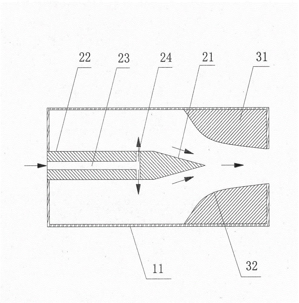
[0028] figure 1 Schematically presents a simplified structural diagram of a discharge device used in an on-site ion source under atmospheric pressure according to an embodiment of the present invention, as shown in figure 1 As shown, the discharge device includes:

[0029] The hollow container 11 is cylindrical; this component is a prior art in the art, and will not be described in detail here;

[0030] A discharge needle, the discharge needle is arranged in the container 11, including a tip portion 21 and a rear end portion 22, the tip portion 21 is conical; the inside of the rear end portion 22 has an axial hole 23 and a diameter that communicate with each other. To the holes 24, the radial holes 24 are evenly distributed; the discharge needle is made of single crystal silicon material;

[0031] Discharge cavity 31, the discharge cavity 31 is cylindrical, along the direction of the tip, the hollow part in the discharge cavity 31 gradually shrinks, and it is arranged on one...


PUM


Abstract

The invention provides a discharging device and method applied to an ion source. The discharging device comprises a hollow container and further comprises a discharging needle, a discharging cavity and a power supply, wherein the discharging needle is arranged in the container and comprises a pointed part and a rear part, an axial hole and radial holes are formed in the rear part, the axial hole is communicated with the radial holes, the radial holes are evenly distributed, the discharging cavity is cylindrical and is formed in one side of the discharging needle in the container, the pointed part stretches into the discharging cavity, the axial section of the discharging cavity is composed of two symmetrical sides, the side, adjacent to the axis, of the section is a curve, the discharging cavity is grounded, and the power supply is formed by introducing high voltage between the discharging needle and the discharging cavity. The discharging device and method applied to the ion source have the advantages that stability is high, sensitivity is high, and service life is long.

Description

technical field [0001] The invention relates to mass spectrometry, in particular to a discharge device and method used in ion sources. Background technique [0002] Among the conventional on-site ion sources under atmospheric pressure, one adopts the method of capillary discharge needle to directly intake air and generate discharge. Although this method is simple to install, it has high discharge voltage requirements and is easy to ignite. Secondly, the airflow jet is concentrated, and the ion jet Large, so it needs a long guide to annihilate ions, which also greatly reduces the number of high-energy particles and reduces the sensitivity of the ion source; in addition, it is introduced from the discharge chamber next to the discharge needle, which is easy to make the gas intake uneven. In addition Due to high-voltage insulation, the overall structure and installation design of the discharge chamber are complicated. At the same time, because the discharge needle is bombarded ...

Claims


Application Information

Patent Timeline
Patent Type & Authority Applications(China)
IPC IPC(8): H01J49/10H01J49/12H01J49/04H01J49/00
Inventor 俞建成闻路红赵鹏胡舜迪孙明超吴勇宁录胜
Owner NINGBO UNIV
Why Eureka
Try Eureka