Automatic inner hole surfacing head

A welding head and inner hole technology, which is applied to welding equipment, welding equipment, arc welding equipment, etc., can solve the problems of difficult operation, long surfacing welding time, glare of arc light, etc., to ensure welding quality, convenient operation, and processing The effect of uniform balance

Inactive Publication Date: 2017-03-15
上海东升焊接集团有限公司 +3
View PDF4 Cites 0 Cited by
  • Summary
  • Abstract
  • Description
  • Claims
  • Application Information

AI Technical Summary

Problems solved by technology

[0010] The technical problem to be solved by the present invention is to provide an automatic inner hole surfacing welding method to overcome the defects in the prior art such as glare of arc light, large smoke and dust, poor visibility, long surfacing welding time and difficult operation due to manual operation of the inner hole. Machine head, the inner hole surfacing welding machine head can be fully automatic operation, suitable for long-term operation, the processing surface is smooth, and the processing allowance is uniform, which not only improves the welding output, but also ensures the welding quality

Method used


Image

  • Automatic inner hole surfacing head
  • Automatic inner hole surfacing head
  • Automatic inner hole surfacing head

Examples


Embodiment 1

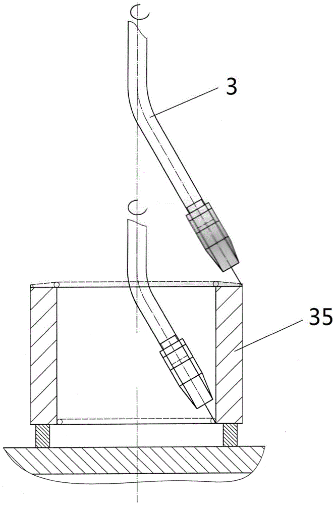
[0031] The invention discloses an automatic inner hole surfacing welding machine head, figure 1 It is a schematic diagram of "one knife drop" of the inner hole and the end face of the surfacing welding. In terms of practicability, the workpiece 35 is mounted on the platform and does not move. This saves the turntable and the transmission device, and the welding torch is lifted, rotated or translated to complete the surfacing welding. arc or plane. Use horizontal welding and vertical pile to achieve the flatness of the weld meat, and use a certain proportion of spiral to achieve a tight arc surface. Welding speed is used to control weld thickness, using diameter When the welding wire is used, the thickness of the welding meat can reach 10mm, and the welding plane can be selected in two forms: manual and automatic.

[0032] In general inner hole surfacing welding, the welding torch 3 rotates and spirals up at the same time. This method is called spiral horizontal welding (suc...

Embodiment 2

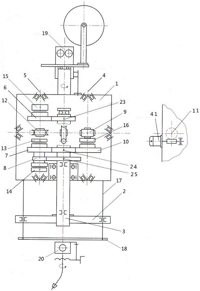
[0044] Such as Figure 4 and Figure 5 Shown is another implementation of the present invention. Including welding torch rotating assembly 33, welding torch lifting assembly 34, lifting screw rod 22, welding torch rotating rod 21, lifting nut 27, lifting driven wheel 31, hand bevel gear 30, lifting nut seat 27, lower positioning sleeve 29, upper positioning Cover 32, welding frame assembly 20.

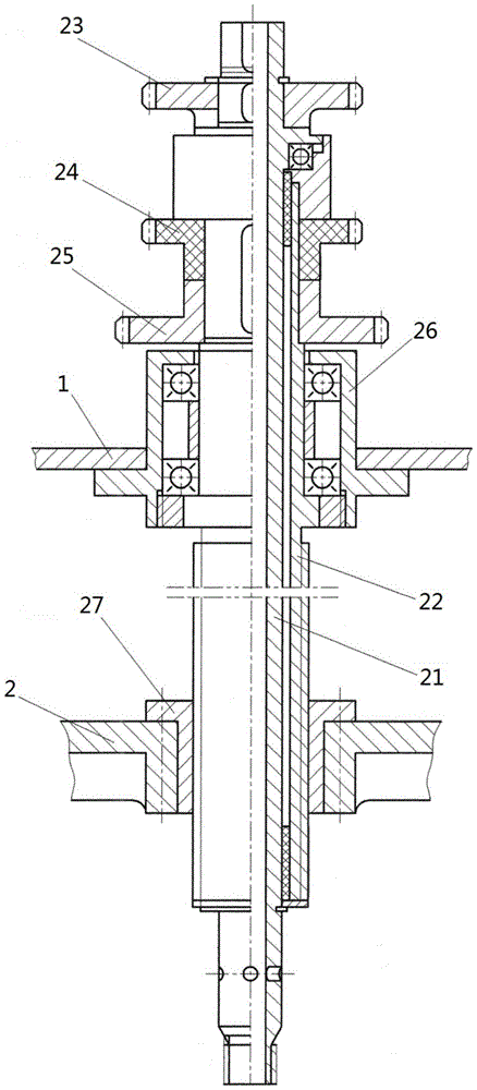
[0045] A welding torch rotating gear 37 is arranged on the welding torch rotating rod 21, and the welding torch rotating gear 37 is driven by a motor and other transmission mechanisms. The lifting screw mandrel 22 is threadedly matched with the lifting nut 27, and the lifting nut 27 is fixedly connected with the lifting driven wheel 31 and the hand bevel gear 30, and the lifting driven wheel 31 can be driven by a motor and a transmission structure.

[0046] The nut drive does not need a drag plate and a fixed transmission box. The rotation of the lifting nut makes the lifting screw ...


PUM


Abstract

The invention discloses an automatic inner bore overlay welding machine head which comprises a lifting screw rod and a welding gun rotating rod, wherein the welding gun rotating rod is arranged in the lifting screw rod in a penetrating manner and can move up and down together with the lifting screw rod; the welding gun rotating rod and the lifting screw rod rotate independently respectively; the welding gun rotating rod is used for connecting with a welding gun. The inner bore overlay welding machine head is capable of realizing full-automatic operation, is applicable to long-time operation, and is flat in finished surface and uniform in processing allowance; according to the inner bore overlay welding machine head, not only can the welding production be improved, but also the welding quality can be ensured.

Description

technical field [0001] The invention relates to an automatic inner hole surfacing welding head, which belongs to the field of welding automation and also belongs to the field of industrial robots. Background technique [0002] Many large machine parts cannot continue to use the worn outer diameter, inner hole or plane, and must be restored to their original shape and precision. For example, it is a pity that a locomotive wheel set and a large part weighing nearly a ton are partially worn out and scrapped. Traditionally, the hole can be repaired by expanding the insert, adding a gasket on the plane, etc. The above method is feasible for light-loaded and low-speed machine parts, but the repair is troublesome and the technical cost is high. [0003] If the high-speed and heavy-duty parts (motorcycle wheelset) use the method of inserting, the reliability will be poor, and it is generally not allowed to use. The application of surfacing welding process is the best repair method,...

Claims


Application Information

Patent Timeline
Patent Type & Authority Patents(China)
IPC IPC(8): B23K9/04B23K9/12B23K37/02
CPCB23K9/042B23K9/12B23K37/0247B23K37/0252
Inventor 岳耀良胡成平胡乐仕
Owner 上海东升焊接集团有限公司
Why Eureka
Try Eureka