Air clamper for bore hole of thin-wall cylinder sleeve

A pneumatic clamping, thin-walled cylinder technology, applied in the direction of clamping device, positioning device, clamping, etc., can solve problems such as workpiece deformation and reduction of machining accuracy

Inactive Publication Date: 2015-04-29
ANHUI WHITE RABBIT POWER
View PDF7 Cites 13 Cited by
  • Summary
  • Abstract
  • Description
  • Claims
  • Application Information

AI Technical Summary

Problems solved by technology

[0003] The reason is that during the clamping process of the cylinder set, the workpiec...

Method used


Image

  • Air clamper for bore hole of thin-wall cylinder sleeve
  • Air clamper for bore hole of thin-wall cylinder sleeve
  • Air clamper for bore hole of thin-wall cylinder sleeve

Examples


Embodiment Construction

[0011] The present invention will be further described below in conjunction with the accompanying drawings.

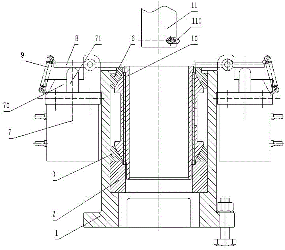
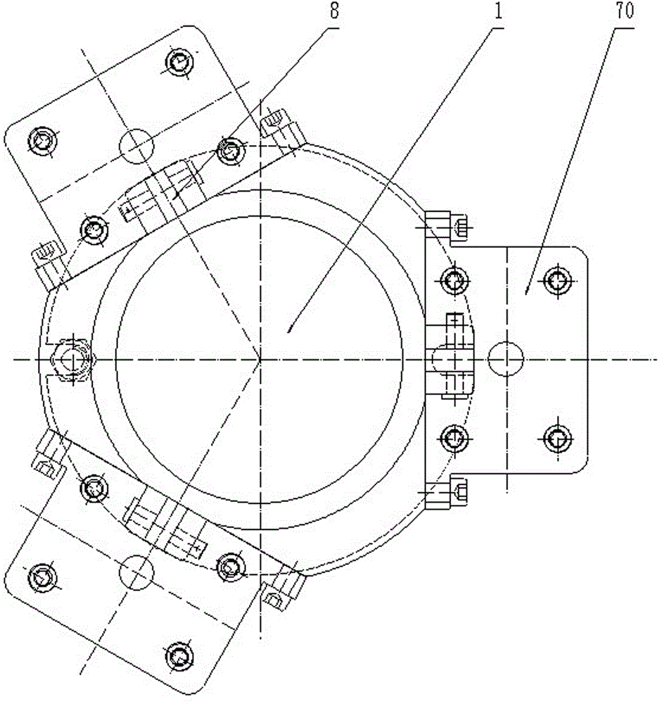
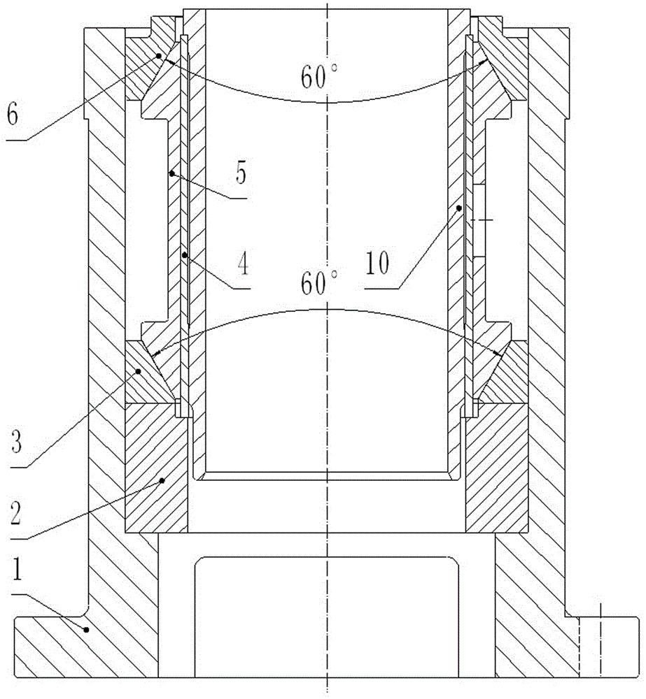
[0012] Such as figure 1 , figure 2 , image 3 It can be seen that the thin-walled cylinder liner boring pneumatic clamping device of the present invention includes a clamp body 1, a backing plate 2 is arranged at the bottom end of the inner cavity of the clamp body 1, and a lower cone with a tapered hole is arranged above the backing plate 2 Sleeve 3, the inner cavity of clamp body 1 above the lower taper sleeve 3 is provided with an elastic split sleeve 4 and a spring sleeve 5 sequentially in the radial direction, and the upper end of the spring sleeve 5 is provided with an upper taper sleeve 6 with a tapered hole, The upper and lower ends of the spring sleeve 5 cooperate with the taper surfaces of the upper taper sleeve 6 and the lower taper sleeve 3 respectively; along the circumferential direction of the clamp body 1, there are three sets of pressing devices uni...


PUM


Abstract

The invention provides an air clamper for a bore hole of a thin-wall cylinder sleeve. The air clamper can steady and clamp the thin-wall cylinder sleeve, a workpiece is uniformly forced in the periphery direction, and deformation does not exist after the thin-wall cylinder sleeve is clamped, so that the processing accuracy is improved. The air clamper comprises a fixture body, wherein base plates are arranged at the bottom end of the inner cavity of the fixture body, lower taper sleeves with taper holes are arranged above the base plates, an elastic open sleeve and a spring sleeve are radially and successively arranged in the inner cavity of the fixture body above the lower taper sleeves, upper taper sleeves with the taper holes are arranged at the upper end of the spring sleeve, and the upper end and the lower end of the spring sleeve are respectively matched with conical surfaces of the upper taper sleeves and the conical surfaces of the lower taper sleeves; at least three sets of compressing devices are uniformly distributed in the periphery direction of the fixture body, and each compressing device comprises a cylinder and a cylinder seat arranged above the cylinder; and pressing arms are arranged on the cylinder seats through pin shafts, piston rods of the cylinders and the pressing arms are mounted in a matching manner, one ends of the pressing arms extend to the edge of the inner cavity of the fixture body, and stretching springs are arranged between the other ends of the pressing arms and the cylinder seats.

Description

technical field [0001] The invention relates to production equipment for auto parts, in particular to a clamping device for a thin-walled cylinder sleeve. Background technique [0002] The processing technology of the inner hole of the thin-walled cylinder liner in the prior art is rough reaming → fine reaming → rough honing → fine honing. Since the precision reaming process is restricted by the manufacturing accuracy and quality of the forming reamer, the roundness of the inner hole of the cylinder liner after reaming can only reach IT9 level, and the honing allowance is 0.3-0.35 mm. With the improvement of engine manufacturers' quality requirements for parts and components, the technical standard for cylinder liners has been upgraded from National III to National IV. The above process capability index has not reached the requirements of National IV. [0003] The reason is that during the clamping process of the cylinder set, the workpiece is deformed due to the unsatisfac...

Claims


Application Information

Patent Timeline
IPC IPC(8): B23Q3/08
CPCB23Q3/08B23Q3/065B23Q2703/04
Inventor 汪舵海孙书义
Owner ANHUI WHITE RABBIT POWER
Why Eureka
Try Eureka