Scanning galvanometer system

A scanning galvanometer system and scanning lens technology, applied in the field of scanning galvanometers, can solve the problems of difficult installation of 45° lenses and very high professional requirements for assembly personnel, and achieve the effect of improving the accuracy of optical path transmission and improving assembly efficiency

Active Publication Date: 2015-04-29
ZHENJIANG JINHAICHUANG TECH
View PDF3 Cites 1 Cited by
  • Summary
  • Abstract
  • Description
  • Claims
  • Application Information

AI Technical Summary

Problems solved by technology

However, the bracket of this patent publication is composed of inner and outer brackets. When assembling, it is necessary to ensure that the positions of the holes of the inner and outer brackets correspond precisely, so the professional requirements for the assemblers are very high; The inner bracket itself is relatively small, so it is very difficult to install the 45° lens

Method used


Image

  • Scanning galvanometer system
  • Scanning galvanometer system
  • Scanning galvanometer system

Examples


Embodiment 1

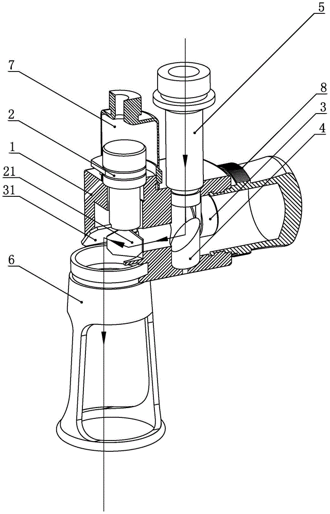
[0023] Such as figure 1 , figure 2 As shown, a scanning galvanometer system includes: a bracket 1, a fixed focus frame 6, an X scanning motor 2, a Y scanning motor 3, a 45° reflector 4, and a light cover 5;

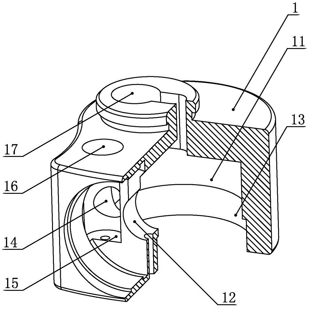
[0024] The upper end of the bracket 1 is vertically provided with an X scanning motor hole 17 and a light-incident sleeve hole 16, the right end is horizontally provided with a Y scanning motor hole 12, and the lower end is vertically provided with a fixed focus frame hole 13; the bracket 1 also includes an inner cavity 11, X scan motor hole 17, Y scan motor hole 12 and fixed focus frame hole 13 respectively penetrate inwardly to the inner cavity 11 of the frame; also includes a light path hole, the axis of the light path hole 14 and the axis of the light hole 16 perpendicularly intersect and merge Parallel to the axis of the Y scanning motor hole 12;

[0025] The X scanning motor 2 includes an X lens 21, the X lens 21 is fixedly connected with the X scanning motor shaft, and...

Embodiment 2

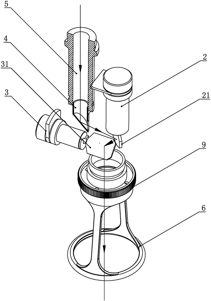
[0031] Such as image 3 , Figure 4 As shown, the second embodiment provides another scanning galvanometer system. There are two differences between the scanning galvanometer system provided in this embodiment and the scanning galvanometer system provided in the first embodiment: First, the 45° in this embodiment The reflector 4 is a hollow tube, the upper end of the 45° reflector 4 is an opening, the bottom end of the inner wall of the 45° reflector 4 is provided with a reflective lens that is inclined at 45° to the horizontal plane, and the side wall of the 45° reflector 4 is provided with a passage The through hole corresponds to the reflective lens, and the 45° reflector 4 is fixedly connected with the bottom end of the light incident sleeve 5. Second, the scanning galvanometer system provided by this embodiment also includes a scanning lens 9. The upper end of the scanning lens 9 is connected to the fixed focus frame hole 13 at the lower end of the bracket 1, and the lower...


PUM


Abstract

The invention discloses a scanning galvanometer system and relates to a scanning galvanometer assembly used for a laser medicine operation or a laser cosmetic surgery, and aims to provide the scanning galvanometer system which is simple in structure, convenient for assembly, and high in precision. The scanning galvanometer system comprises a bracket, a focus fixing frame, an X-scanning motor, a Y-scanning motor, a 45-degree reflector, and a light inlet sleeve, wherein an X-scanning motor hole and a light inlet sleeve hole are formed in the upper end of the bracket, a Y-scanning motor hole is formed in the right end of the bracket, a focus fixing frame hole is formed in the lower end of the bracket, the X-scanning motor, the Y-scanning motor, the focus fixing frame and the light inlet sleeve are respectively correspondingly mounted in corresponding bracket holes, the X-scanning motor comprises an X-lens, the X-lens is fixedly connected with a shaft of the X-scanning motor, the Y-scanning motor comprises a Y-lens, the Y-lens is fixedly connected with a shaft of the Y-scanning motor, and two mounting modes of the reflector are provided.

Description

Technical field [0001] The invention relates to a light direction control device, in particular to a scanning galvanometer used for laser medical surgery or laser cosmetic surgery. Background technique [0002] The galvanometer system is a high-precision, high-speed servo control system composed of a drive plate and a high-speed swing motor. It is mainly used in laser marking, laser internal engraving, stage lighting control, laser drilling, dot matrix laser medical beauty industry Wait. At present, most galvanometer systems in the world work in a static mode. After the laser emits light horizontally, it passes through the beam expander and enters the scanning galvanometer system, and the falling point of the light is controlled by the swing of the X and Y mirrors. However, if the scanning galvanometer is in motion and controlled by the handheld mode, the original light-in / out method is very inconvenient to apply. [0003] Chinese patent CN201384793Y discloses a technology that p...

Claims


Application Information

Patent Timeline
Patent Type & Authority Applications(China)
IPC IPC(8): G02B26/10G02B7/182
Inventor 周双留刘晓东
Owner ZHENJIANG JINHAICHUANG TECH
Why Eureka
Try Eureka