Method for implementing multi-azimuth electromagnetic wave low-frequency conversion by using Dirac point difference frequency effect

A technology of Dirac point and difference frequency effect, which can be used in optical demodulation, optics, instruments, etc., and can solve the problems of complex process, harsh operating conditions and low conversion efficiency.

Active Publication Date: 2015-04-29
UNIVERSITY OF CHINESE ACADEMY OF SCIENCES
View PDF3 Cites 11 Cited by
  • Summary
  • Abstract
  • Description
  • Claims
  • Application Information

AI Technical Summary

Problems solved by technology

[0012] Aiming at the shortcomings of the existing laser nonlinear frequency conversion method, such as complicated process, harsh operating conditions and low conversion efficiency, the invention provides a simple, flexible, accurate and efficient realization by using the difference frequency effect of photonic crystals near the frequency of the Dirac point The method of multi-directional electromagnetic wave low-frequency conversion aims to break through the bottleneck faced by the existing optical difference frequency oscillation technology

Method used


Image

  • Method for implementing multi-azimuth electromagnetic wave low-frequency conversion by using Dirac point difference frequency effect
  • Method for implementing multi-azimuth electromagnetic wave low-frequency conversion by using Dirac point difference frequency effect
  • Method for implementing multi-azimuth electromagnetic wave low-frequency conversion by using Dirac point difference frequency effect

Examples


Embodiment 1

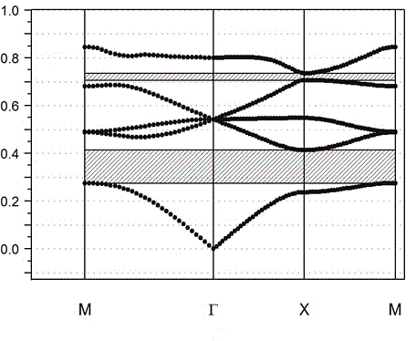
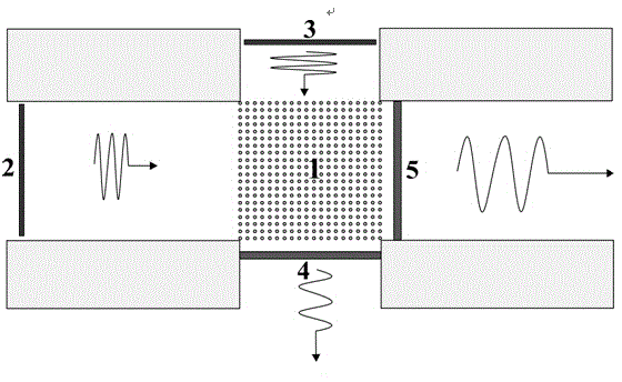
[0050] Choose a two-dimensional photonic crystal, set the lattice period of the photonic crystal as a, by Al 2 o 3 Dielectric pillars (dielectric constant ε=12.5) are periodically arranged in a square lattice structure in an air background (purity>99%, ε=1), with a radius of 0.2a and a filling ratio of 12.6%. figure 1 Given the energy band structure diagram of the photonic crystal array, it can be seen that the relative frequency of the Dirac point is ω 0 = 0.54. The photonic crystal is cut along the direction of the square lattice period to obtain a 20×20 two-dimensional photonic crystal square array (forming a photonic crystal block), which is symmetrically placed on the upper, lower, left, and right four outgoing and incoming metal waveguides in the middle, get figure 2 The low frequency oscillation generating device shown. On the upper and lower sides of the photonic crystal array 1, a Dirac point frequency wave source 3 and a vertical direction outgoing wave field de...

Embodiment 2

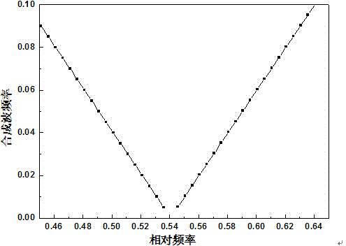
[0056] Using the same low-frequency oscillation generating device as in Example 1, the Dirac point frequency is still ω 0 =0.54, corresponding to the actual incident frequency of 16.2GHz, the difference is that when the relative frequency of the horizontal incident wave is 0.53 which is closer to the frequency of the Dirac point, it corresponds to the actual horizontal incident frequency of 15.9GHz, the two are in the photonic crystal block In superposition, using the difference frequency effect, the detected wave form of the outgoing wave in the horizontal direction changing with time is shown in Figure 5(a), and the wave form of the detected outgoing wave in the vertical direction changing with time is shown in Figure 5(b ) shows that not only the frequencies are equal, but also the amplitudes are basically the same. The low-frequency oscillation frequency of the synthesized wave is 0.3GHz, which is more than 50 times lower than that of the incident wave.

Embodiment 3

[0058] Using the same low-frequency oscillation generating device as in Embodiment 1, the Dirac point frequency is still 16.2 GHz. The difference is that when the relative frequency of the horizontal incident wave continues to decrease, it is ω=0.48 away from the Dirac point frequency, which corresponds to the actual The frequency of the horizontal incident wave is 14.4GHz, and the two are superimposed in the photonic crystal block. Using the difference frequency effect, the detected waveforms of the horizontal and vertical outgoing waves changing with time are as follows: Image 6 As shown, the low-frequency oscillation frequency of the synthesized wave is 1.8GHz. It can be seen that the greater the frequency difference with the Dirac point frequency, the greater the frequency of the outgoing wave after modulation, and the smaller the amplitude of the outgoing wave in the vertical direction. Because the amplitude is too small, its low-frequency oscillation is basically difficu...


PUM

PropertyMeasurementUnit
densityaaaaaaaaaa

Abstract

The invention provides a method for implementing multi-azimuth electromagnetic wave low-frequency conversion by using a Dirac point difference frequency effect. A beam of waves with Dirac point frequency illuminates a photonic crystal array along the vertical direction; another beam of waves without Dirac point frequency penetrates in the photonic crystal array along different directions and is in a transmission state; the two beams of waves are superposed in the photonic crystal array so that difference frequency oscillation is caused; light wave energy is re-distributed; two beams of waves are converted into two beams of low-frequency signals with the same frequency along different azimuths under the effect of a difference frequency effect; and the two beams of low-frequency signals are transmitted outwards. By the method, the difference frequency effect is achieved by two beams of high-frequency incident light coming from different azimuths creatively, multi-azimuth low-frequency outgoing waves with the same frequency are obtained, and a machining process is simplified. The method has the advantages of low loss, low cost, high conversion efficiency, easiness and convenience in operation and the like, and is suitable for performing low-frequency oscillation conversion on any materials with Dirac point characteristics. Electromagnetic waves and sound waves which correspond to photonic crystal energy band structures are in a frequency conversion range.

Description

technical field [0001] The invention relates to a method for realizing low-frequency conversion of electromagnetic waves, which belongs to the technical field of electromagnetic wave or optical frequency conversion. Background technique [0002] Light is an electromagnetic wave of a specific wavelength, which carries energy in the form of photons for propagation. It is the quantum of the electromagnetic field and the propagator that transmits the electromagnetic interaction. Photons have fast switching speed, large information capacity, no electromagnetic interference, and high integration, which make them have a wide range of application values ​​in optical communication, optical computing, optical detection and other fields. Photons of different frequencies have different energies. In order to realize energy exchange between different frequencies of light, people usually use various gain media, such as helium-neon, ruby, semiconductor, etc., to prepare lasers of different ...

Claims


Application Information

Patent Timeline
Patent Type & Authority Applications(China)
IPC IPC(8): G02F2/02
CPCG02F2/02
Inventor 董国艳
Owner UNIVERSITY OF CHINESE ACADEMY OF SCIENCES
Why Eureka
Try Eureka