A Method of Realizing Low-Frequency Conversion of Multi-Aspect Electromagnetic Waves Using Dirac Point Difference Frequency Effect
A technology of Dirac point and difference frequency effect, which can be used in optical demodulation, optics, instruments, etc., and can solve the problems of complex process, low conversion efficiency and harsh operating conditions.
- Summary
- Abstract
- Description
- Claims
- Application Information
AI Technical Summary
Problems solved by technology
Method used
Image
Examples
Embodiment 1
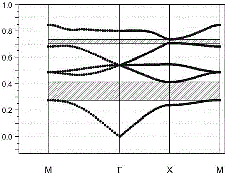
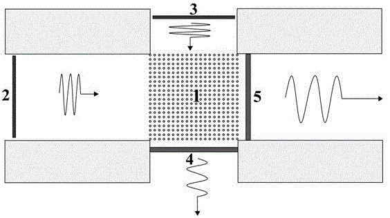
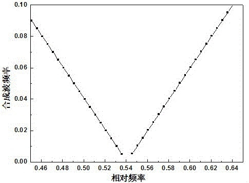
[0050] Choose a two-dimensional photonic crystal, set the lattice period of the photonic crystal as a, by Al 2 o 3 Dielectric pillars (dielectric constant ε=12.5) are periodically arranged in a square lattice structure in an air background (purity>99%, ε=1), with a radius of 0.2a and a filling ratio of 12.6%. figure 1 Given the energy band structure diagram of the photonic crystal array, it can be seen that the relative frequency of the Dirac point is ω 0 = 0.54. The photonic crystal is cut along the direction of the square lattice period to obtain a 20×20 two-dimensional photonic crystal square array (forming a photonic crystal block), which is symmetrically placed on the upper, lower, left, and right four outgoing and incoming metal waveguides in the middle, get figure 2 The low frequency oscillation generating device shown. On the upper and lower sides of the photonic crystal array 1, a Dirac point frequency wave source 3 and a vertical direction outgoing wave field de...
Embodiment 2
[0056] Using the same low-frequency oscillation generating device as in Example 1, the Dirac point frequency is still ω 0 =0.54, corresponding to the actual incident frequency of 16.2GHz, the difference is that when the relative frequency of the horizontal incident wave is 0.53 which is closer to the frequency of the Dirac point, it corresponds to the actual horizontal incident frequency of 15.9GHz, the two are in the photonic crystal block In superposition, using the difference frequency effect, the detected wave form of the outgoing wave in the horizontal direction changing with time is shown in Figure 5(a), and the wave form of the detected outgoing wave in the vertical direction changing with time is shown in Figure 5(b ) shows that not only the frequencies are equal, but also the amplitudes are basically the same. The low-frequency oscillation frequency of the synthesized wave is 0.3GHz, which is more than 50 times lower than that of the incident wave.
Embodiment 3
[0058] Using the same low-frequency oscillation generating device as in Embodiment 1, the Dirac point frequency is still 16.2 GHz. The difference is that when the relative frequency of the horizontal incident wave continues to decrease, it is ω=0.48 away from the Dirac point frequency, which corresponds to the actual The frequency of the horizontal incident wave is 14.4GHz, and the two are superimposed in the photonic crystal block. Using the difference frequency effect, the detected waveforms of the horizontal and vertical outgoing waves changing with time are as follows: Image 6 As shown, the low-frequency oscillation frequency of the synthesized wave is 1.8GHz. It can be seen that the greater the frequency difference with the Dirac point frequency, the greater the frequency of the outgoing wave after modulation, and the smaller the amplitude of the outgoing wave in the vertical direction. Because the amplitude is too small, its low-frequency oscillation is basically difficu...
PUM
| Property | Measurement | Unit |
|---|---|---|
| density | aaaaa | aaaaa |
Abstract
Description
Claims
Application Information
 - R&D
- Intellectual Property
- Life Sciences
- Materials
- Tech Scout
- Unparalleled Data Quality
- Higher Quality Content
- 60% Fewer Hallucinations
Browse by: Latest US Patents, China's latest patents, Technical Efficacy Thesaurus, Application Domain, Technology Topic, Popular Technical Reports.
© 2025 PatSnap. All rights reserved.Legal|Privacy policy|Modern Slavery Act Transparency Statement|Sitemap|About US| Contact US: help@patsnap.com


