
Pilotless automobile lateral control method based on turning curvature estimation

A lateral control, unmanned vehicle technology, applied in two-dimensional position/channel control and other directions, can solve the problems such as the control volume is not smooth enough, the lateral error of the preview point has a large influence, and the steering wheel angle is abruptly changed.

Active Publication Date: 2015-04-29
HEFEI INSTITUTES OF PHYSICAL SCIENCE - CHINESE ACAD OF SCI
View PDF4 Cites 65 Cited by
  • Summary
  • Abstract
  • Description
  • Claims
  • Application Information

AI Technical Summary

Problems solved by technology

Although this control method can also enable unmanned vehicles to realize the tracking function of the predetermined trajectory, and has a certain ability to adapt to changes in road curvature characteristics, it can only describe the shape of the road near the vehicle approximately, but cannot accurately To describe the curvature of the road, in the steering control, the lateral error PID (proportional differential-integral) control of the single-point preview is used so that the control amount is greatly affected by the lateral error of the preview point. When there is a jump in the preview point, it is very It is easy to cause sudden changes in the steering wheel angle, resulting in insufficient smoothness of the control volume

Method used


Image

  • Pilotless automobile lateral control method based on turning curvature estimation
  • Pilotless automobile lateral control method based on turning curvature estimation
  • Pilotless automobile lateral control method based on turning curvature estimation

Examples


Embodiment Construction

[0041] The preferred mode of the present invention will be described in further detail below in conjunction with the accompanying drawings.

[0042] The vehicle used in this embodiment is the "Tiggo" car of Wuhu Chery, China, and it is equipped with the GPS-INS combined positioning system of NovAtel's SPAN-CPT and the model of Zhongke Automation It is an autopilot of IPD1 and a microcomputer as an industrial computer. Among them, the GPS-INS combined positioning system is used to obtain the latitude and longitude, vehicle speed signal, and vehicle heading angle signal of the vehicle's location to send to the industrial computer; when the system uses differential positioning, it provides a positioning accuracy of 0.1m . The autopilot is connected to the industrial computer through the CAN bus, and is used to receive the vehicle speed control signal and the steering wheel angle command signal from the industrial computer.

[0043] See figure 1 , The workflow of the unmanned vehicl...


PUM


Abstract

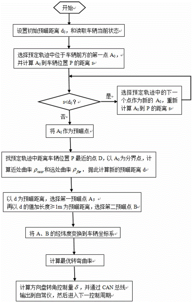
The invention discloses a pilotless automobile lateral control method based on turning curvature estimation. The pilotless automobile lateral control method based on the turning curvature estimation comprises setup of a preconceived track, collection of GPS-INS integrated positioning system data and steering wheel turning angle command signals send out by an autopilot, and especially is a method that a preview distance based on a road curvature is set firstly, and then a preview point A and a preview point B are reset according to the preview distance, later, longitudes and latitudes of the preview point A and the preview point B are converted into a vehicle coordinate system to work out an optimum turning curvature, and steering wheel turning angle controlled quantity is worked out according to the optimum turning curvature and is output to the autopilot to achieve lateral control of a pilotless automobile. According to the pilotless automobile lateral control method based on the turning curvature estimation, through actual measurement, the maximum tracking error is only 0.4m when the speed of the automobile is at 20km / h, the maximum tracking error is only 0.6m when the speed of direction change is 5km / h; both accurate tracking of various kinds of complex tracks is achieved, and steering wheel shaking caused by single-point preview feedback control is avoided, and the control quantity of the pilotless automobile is more smooth; the method can be widely used in pilotless driving control of the various kinds of vehicles.

Description

Technical field [0001] The invention relates to an unmanned vehicle lateral control method, in particular to an unmanned vehicle lateral control method based on the estimation of the turning rate. Background technique [0002] Unmanned vehicles are one of the development trends of smart vehicles in the future. Research on unmanned vehicles will also promote the development of smart transportation and smart cities, which is of great strategic significance. To this end, many institutions at home and abroad have launched research and development work on unmanned vehicles, such as the Chinese invention patent CN 102495631B announced on August 21, 2013, an intelligent control method for unmanned vehicles to track a predetermined trajectory. This method is based on the installed on-board computer, GPS-INS combined positioning system and the vehicle steering and speed servo control system controlled by the on-board computer. The computer control method that uses the waypoint coordinate...

Claims


Application Information

Patent Timeline
Patent Type & Authority Applications(China)
IPC IPC(8): G05D1/02
Inventor 刘跃宋彦梁华为梅涛
Owner HEFEI INSTITUTES OF PHYSICAL SCIENCE - CHINESE ACAD OF SCI
Learn More