Liquid circuit built-in aluminium air fuel cell monomer and cell stack

A fuel cell and built-in technology, applied in the direction of fuel cells, fuel cell half-cells, primary battery half-cells, fuel cell groups, etc., can solve the problems of not finding, inconvenient operation, and not finding invention cases, etc. To achieve the effect of reducing the distance

Inactive Publication Date: 2015-04-29
PLA SECOND ARTILLERY ENGINEERING UNIVERSITY
View PDF9 Cites 27 Cited by
  • Summary
  • Abstract
  • Description
  • Claims
  • Application Information

AI Technical Summary

Problems solved by technology

Although the aluminum-air fuel cell has many advantages, its current monomer structure has the following disadvantages: First, the traditional monomer liquid delivery is realized by adding many electrolyte liquid pipes, and each monomer has a liquid inlet channel. The pipes and one outlet liquid pipe have complex structures, low degree of engineering, complicated guarantee, inconvenient operation, and many liquid pipe interfaces; the second is that the positive and negative electrodes of the traditional monomer are connected by welding the connecting wires on the The conductive current collector of the air electrode is realized from above. This method has a low degree of engineering, and is bonded after manual welding. The manufacturing process of the monomer is complicated, inconvenient to operate, and not beautiful. The third is that the traditional monomer air electrode and the monomer matrix frame are sealed with AB

Method used


Image

  • Liquid circuit built-in aluminium air fuel cell monomer and cell stack
  • Liquid circuit built-in aluminium air fuel cell monomer and cell stack
  • Liquid circuit built-in aluminium air fuel cell monomer and cell stack

Examples


Embodiment Construction

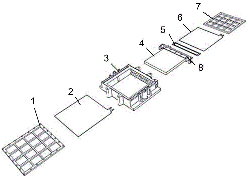
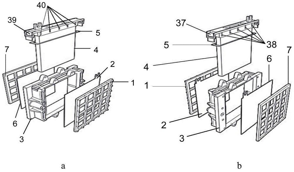
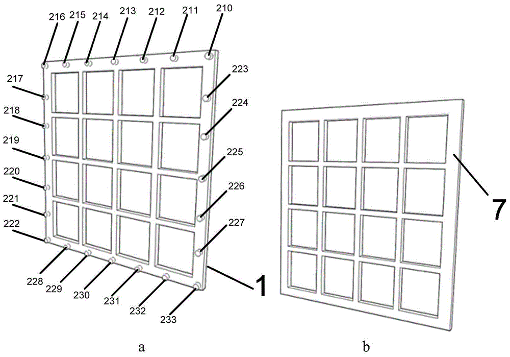
[0039] The present invention will be described in further detail below in conjunction with the accompanying drawings.

[0040] see Figure 1-10 According to the present invention, a single aluminum-air fuel cell with a built-in liquid circuit includes a single grid, an air cathode, a basic frame 3 and an anode aluminum alloy electrode 4 covered with a sealing ring 5 . The single grid includes the first and second flat grids 1, 7, and the edge of the first flat grid is uniformly arranged with a number of top pillars. The air cathode includes the first air electrode 2 and the second air electrode 6; and the built-in liquid circuit aluminum The specific structure of the air fuel cell unit includes the first flat grid 1, the first air electrode 2, the base frame 3, the second air electrode 6 and the second flat grid 7 arranged in sequence; There is a side port for inserting the anode aluminum alloy electrode 4, and the outside of the basic frame 3 is also provided with a first el...


PUM


Abstract

The invention relates to a liquid circuit built-in aluminium air fuel cell monomer and a cell stack. The liquid circuit built-in aluminium air fuel cell monomer comprises a first flat grid mesh, a first air electrode, a matrix frame, a second air electrode and a second flat grid mesh which are sequentially arranged, wherein the first air electrode is used as a cathode; the matrix frame is provided with a side port for enabling an aluminium alloy electrode used as an anode to be inserted in; a first electrolyte pipe orifice and a second electrolyte pipe orifice are also formed outside the matrix frame. The cell stack comprises a plurality of liquid circuit built-in aluminium air fuel cell monomers which are connected in series and a gap is reserved between every two adjacent cell monomers; support pillars are arranged at the edges of the first flat grid meshes; the first electrolyte pipe orifice in each cell monomer is connected with the second electrolyte pipe orifice in the adjacent cell monomer; the first and second air electrodes in each cell monomer are connected with the aluminium alloy electrode used as the anode in the adjacent cell monomer. According to the invention, a fuel cell pipeline is simple, the engineering degree is high, the guarantee is simple, the operation is convenient, the processing consistency is good, and the recycling and reusing can be realized.

Description

technical field [0001] The invention belongs to the technical field of fuel cells, and in particular relates to a liquid-path built-in aluminum-air fuel cell unit and a cell stack. Background technique [0002] Aluminum-air battery uses active metal aluminum as fuel source, air or oxygen as oxidant, alkaline solution or neutral salt solution as electrolyte, and converts chemical energy stored in metal aluminum into electrical energy through electrochemical reaction. Although the aluminum-air fuel cell has many advantages, its current monomer structure has the following disadvantages: First, the traditional monomer liquid delivery is realized by adding many electrolyte liquid pipes, and each monomer has a liquid inlet channel. The pipes and one outlet liquid pipe have complex structures, low degree of engineering, complicated guarantee, inconvenient operation, and many liquid pipe interfaces; the second is that the positive and negative electrodes of the traditional monomer a...

Claims


Application Information

Patent Timeline
IPC IPC(8): H01M12/06H01M8/02H01M4/86H01M8/24
CPCH01M4/86H01M8/006H01M8/0271H01M8/249H01M12/065H01M2004/8684Y02E60/50
Inventor 蔡艳平李艾华徐斌王涛赵军红
Owner PLA SECOND ARTILLERY ENGINEERING UNIVERSITY
Why Eureka
Try Eureka