A permanent magnet brushless DC motor for electric vehicles with offset mounting structure

An installation structure, permanent magnet DC technology, applied in electric vehicles, synchronous motors with stationary armatures and rotating magnets, motors, etc., can solve the size restrictions of the built-in magnetic ring and stator assembly, and the influence of the radius of gyration of the motor , motor service life reduction and other issues, to improve the dustproof and waterproof function, optimize the internal space structure, improve the effect of service life

Active Publication Date: 2016-03-23
TAIZHOU JINYU ELECTROMECHANICAL
View PDF5 Cites 2 Cited by
  • Summary
  • Abstract
  • Description
  • Claims
  • Application Information

AI Technical Summary

Problems solved by technology

Considering the overall convenience of electric vehicles, the tires of electric vehicles are usually relatively small, and the outer diameter of the motor rim is affected by the installation size of the tires, resulting in restrictions on the size of the built-in magnetic ring and the size of the stator assembly. The permanent magnet brushless motor is usually installed in a symmetrical structure, and its rotor assembly and stator assembly are usually placed in the middle of the motor, which affects the radius of the motor's gyration. The motor is the driving core of the electric vehicle. During operation, it is very easy to have a large load or overload, which will reduce the service life of the motor and cause a high failure rate
At the same time, when the existing ordinary permanent magnet brushless motor for electric vehicles is running in a rainy day or in a dusty environment, the internal air pressure of the motor will increase due to the temperature rise during continuous operation. The air pressure difference will cause external water vapor or dust to enter the motor through the tiny gap of the motor, which will reduce the insulation performance of the motor and affect the service life of the motor

Method used


Image

  • A permanent magnet brushless DC motor for electric vehicles with offset mounting structure
  • A permanent magnet brushless DC motor for electric vehicles with offset mounting structure
  • A permanent magnet brushless DC motor for electric vehicles with offset mounting structure

Examples


Embodiment 1

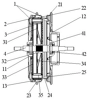
[0026] According to the above-mentioned overall structure, the optimal pole slot ratio of the rotor assembly and the stator assembly of the present invention is 48 poles and 54 slots, and the use of 48 pole permanent magnets can reduce the iron loss of the motor and obtain excellent overall efficiency. Combining the current density of the winding and the iron The maximum magnetic field density of the core adopts the best 54 slot structure, and the slot surface area adopts 75~90mm 2 , the structure ratio improves the overall efficiency of the motor, and has the characteristics of high-speed type.

Embodiment 2

[0028] According to the above-mentioned overall structure, the optimal pole slot ratio of the rotor assembly and the stator assembly of the present invention is 60 poles and 54 slots, and the use of 60 poles permanent magnets can reduce the positioning torque of the motor and obtain an excellent overall torque effect. Combined with the winding current density The best 54-slot structure is selected for the maximum magnetic field density of the iron core, and the slot surface area is 75~90mm 2 , the structure ratio improves the overall efficiency of the motor, and has the characteristics of torque type.

Embodiment 3

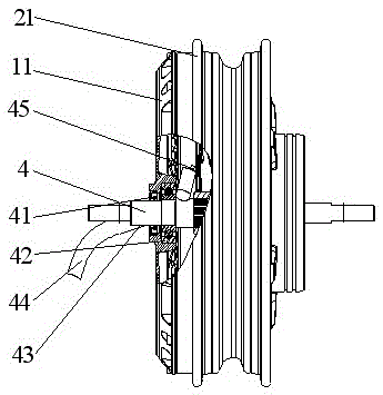
[0030] According to the above overall structure, such as Figure 4 As shown, the rim 21 of the present invention can be made of aluminum alloy casting, and the original rim 21 is replaced by the structure of the aluminum alloy rim 5. The middle part of the structure of the aluminum alloy rim 5 is also provided with an aluminum alloy groove bottom 54, which is an asymmetric rounded structure. It has a structure of two rounded corners, one large and one small. The left side of the aluminum alloy rim 5 is provided with a connection platform 51, and the left side of the inner surface of the connection platform 51 is provided with a fixed end cover positioning notch 52 to complete the positioning and installation of the fixed end cover 11. At the same time, the fixed end cover 11 and the left side of the connection table 52 are fastened and connected by fastening screws 53. The inner surface of the connection table 51 is connected with the magnetic guide ring 23, and a fastening tab...


PUM


Abstract

A permanent magnetic direct-current brushless motor of a biased mounting structure comprises an end cap, a rotor assembly, a stator assembly and a motor shaft. The end cap is positioned on two sides of the rotor assembly and composed of a fixed end cap and a drum brake end cap, the rotor assembly is composed of a wheel rim, a magnetic conducting ring in left biased mounting, a fixing ring and a permanent magnet and mounted with the stator assembly in a matched manner, the stator assembly is composed of an iron core and a through groove used for mounting of a winding, silicon steel sheets are arranged on the outer circumference of the iron core and are of a stacked structure, a fixing shaft sleeve is arranged at the center of the iron core in a right biased manner, a fixing support is arranged on the outer circumferential side of the fixing shaft sleeve, the fixing shaft sleeve and the motor shaft are in interference fit, and a knurled structure is arranged at a position where the motor shaft and the fixing shaft sleeve are connected. A motor structure is designed in an optimized manner, and a biased mounting mode is adopted, so that diameter size of the stator assembly and the rotor assembly is increased, key performance parameters like torque and efficiency of the motor are enhanced, and load-carrying capacity of a whole vehicle is improved.

Description

technical field [0001] The present invention relates to the technical field of electric vehicle motors. Specifically, the present invention relates to a permanent magnet brushless DC motor for electric vehicles with an offset mounting structure. Background technique [0002] The motor is one of the core components of an electric vehicle. The performance of the electric vehicle motor directly affects the safety, operability, reliability and service life of the electric vehicle. Considering the overall convenience of electric vehicles, the tires of electric vehicles are usually relatively small, and the outer diameter of the motor rim is affected by the installation size of the tires, resulting in restrictions on the size of the built-in magnetic ring and the size of the stator assembly. The permanent magnet brushless motor is usually installed in a symmetrical structure, and its rotor assembly and stator assembly are usually placed in the middle of the motor, which affects th...

Claims


Application Information

Patent Timeline
Patent Type & Authority Patents(China)
IPC IPC(8): H02K21/24H02K1/28H02K5/10H02K1/16
CPCY02T10/64
Inventor 王加许丁伟马洪杰
Owner TAIZHOU JINYU ELECTROMECHANICAL
Why Eureka
Try Eureka