
A dual-channel control hydraulic motor type active stabilizer bar system

A technology of active stabilizer bar and hydraulic motor, which is applied in the field of vehicle safety, can solve the problems of low load capacity, high pressure leakage, affecting comfort and safety, etc., and achieve high driving safety, hydraulic system safety, and great control simplicity Effect

Active Publication Date: 2017-01-11
HEFEI UNIV OF TECH
View PDF5 Cites 0 Cited by
  • Summary
  • Abstract
  • Description
  • Claims
  • Application Information

AI Technical Summary

Problems solved by technology

In China, automobile companies have not independently developed and manufactured active stabilizer bar systems. Most off-road vehicles use conventional stabilizer bars; The body will produce a large roll, affecting comfort and safety
An active anti-roll stabilizer bar solution in the prior art: the swing motor adopts a double-vane swing motor, which has the disadvantages of high pressure leakage, low load-carrying capacity, poor impact resistance, and excessive weight; the hydraulic system adopts the front axle The pressure valve and the rear axle pressure valve are connected in series to control the pressure of the front and rear axle motors. This solution limits the independence of the pressure control of the front and rear two motors. The performance is that the pressure of the rear hydraulic motor is always less than or equal to the pressure of the front hydraulic motor, especially for off-road vehicles. Appears as understeer when turning, reducing vehicle agility

Method used


Image

  • A dual-channel control hydraulic motor type active stabilizer bar system
  • A dual-channel control hydraulic motor type active stabilizer bar system

Examples


Embodiment

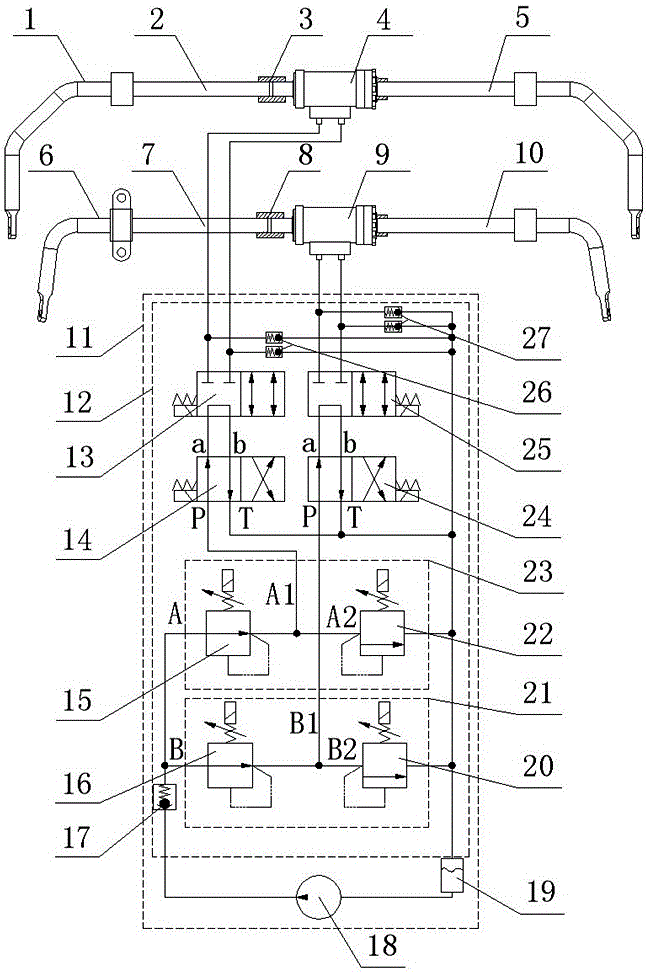
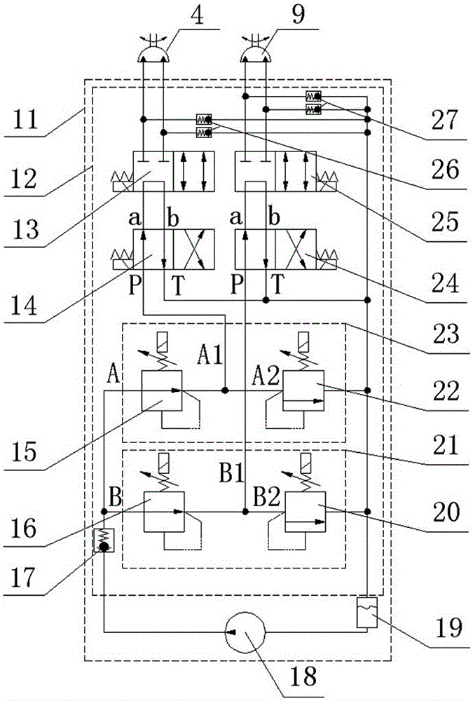
[0024] see figure 1 , a dual-channel control hydraulic motor type active stabilizer bar system includes a front stabilizer bar mechanism 1 , a rear stabilizer bar mechanism 6 and a hydraulic control mechanism 11 . The front stabilizer bar mechanism 1 includes the front left stabilizer half rod 2, the front right stabilizer half rod 5 and the front hydraulic motor 4; the front hydraulic motor 4 is connected in series between the front left stabilizer half rod 2 and the front right stabilizer half rod 5; The stabilizer half rod 2 is welded to the output shaft of the front hydraulic motor through the front sleeve 3, and the front right stabilizer half rod 5 is welded to the rear end cover of the front hydraulic motor. The rear stabilizer bar mechanism 6 includes a rear left stabilizer half rod 7, a rear right stabilizer half rod 10 and a rear hydraulic motor 9; the rear hydraulic motor 9 is connected in series between the left stabilizer half rod 7 and the rear right stabilizer h...


PUM


Abstract

The invention relates to a double-channel control hydraulic motor type initiative stabilizing rod system which comprises a front stabling rod mechanism, a rear stabling rod mechanism and a hydraulic control mechanism, wherein the front stabling rod mechanism and the rear stabling rod mechanism both comprise a left stabilizing half-rod, a right stabilizing half-rod and a hydraulic motor; the hydraulic motor is serially connected between the left stabilizing half-rod and the right stabilizing half-rod; the front and rear hydraulic motors are both arranged as spiral swinging hydraulic motors; the hydraulic control mechanism comprises an overlapping type hydraulic integrated valve, a hydraulic oil pump and a hydraulic oil tank; the overlapping type hydraulic integrated valve is composed of a check valve, front and rear pressure control valve sets, front and rear directional valves, a safety valve and a check valve; the front and rear pressure control valve sets are both formed by serially connecting an electromagnetic proportional pressure-reducing valve with an electromagnetic proportional overflow valve; the hydraulic control mechanism is respectively connected with the hydraulic motors in the front stabling rod mechanism and the rear stabling rod mechanism through hydraulic oil ways, so that the front and rear double-channel control is realized. The double-channel control hydraulic motor type initiative stabilizing rod system can initiatively control and adjust the vehicle body in real time when the vehicle body heels and can supply the optimal comfort, higher safety and higher operation simplification to a driver.

Description

technical field [0001] The invention belongs to the technical field of vehicle safety, and in particular relates to an active stabilizer bar system. Background technique [0002] For off-road vehicles, the chassis system must provide the driver with the best driving comfort, high driving safety and maximum handling simplicity, among which vehicle roll is one of the important factors affecting comfort and safety. As an important safety part of the independent suspension system of the car, the stabilizer bar can improve the stability of the operation when the car turns or encounters resistance, and prevents the body from excessive lateral roll. The existing anti-rolling bar provides passive anti-rolling torque when the vehicle rolls, and the torque is not adjustable; the vehicle is prone to roll when the speed is high and the steering is high, which will cause a decrease in comfort when driving straight, and it is difficult to satisfy the ride comfort at the same time Require...

Claims


Application Information

Patent Timeline
Patent Type & Authority Patents(China)
IPC IPC(8): B60G21/055
Inventor 黄康郜欣欣高峰邵可晏伟清黄青青
Owner HEFEI UNIV OF TECH
Learn More