Plastic wire drawing machine with wire swing mechanism
A technology of plastic wire drawing machine and cooling mechanism, which is applied in the direction of drawing spinning, filament generation, textile and paper making, etc. It can solve the problems of long cooling time, accelerated cooling of plastic wire, and low space utilization, so as to improve the cooling effect , high cooling efficiency, good cooling effect
- Summary
- Abstract
- Description
- Claims
- Application Information
AI Technical Summary
Problems solved by technology
Method used
Image
Examples
Embodiment 1
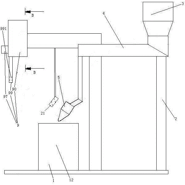
[0044] Embodiment one, see figure 1 , a plastic wire drawing machine provided with a wire-swing mechanism, comprising a frame 2, a feed barrel 3, a barrel 4, a die head 5, a cooling mechanism 1 and a wire-swing mechanism 9.
[0045] The frame 2 is provided with a guide ring 21 . The feeding barrel 3 is fixed on the frame 2. Feeding barrel 3 is a funnel structure. The lower end of the feeding barrel 3 is connected with the inlet end of the barrel 4 . The outlet end of the barrel 4 is connected with the die head 5 . The cooling mechanism 1 includes a cooling water bucket 12 . The cooling water bucket 12 is located below the die head 5 .
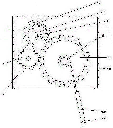
[0046] The spinning mechanism 9 includes a box body 90 , a swing rod 99 and a motor 97 . The box body 90 is fixedly connected with the frame 2 . The lower end of the swing rod 96 is provided with a threading hole 991 .
[0047] see figure 2 The spinning mechanism 9 also includes a power input shaft 96 , a swing shaft 91 , a swing gear...
Embodiment 2
[0051] Embodiment two, the difference with embodiment one is:
[0052] see Figure 4 , also includes a water pump 7 and a nozzle 8. The feed bucket 3 includes an outer tank body 31 , an inner tank body 32 and an isolation floating plate 33 .
[0053] The outer tank body 31 is arranged on the base of the frame 2 . The outer tank body 31 has an open upper end structure. The upper end of the outer tank body 31 is provided with a water inlet pipe 311 . A water inlet valve 312 is disposed in the water inlet pipe 311 . The lower end of the outer tank body 31 is provided with a drain pipe 313 . A drain valve 314 is provided in the drain pipe 313 . A supporting frame 315 is arranged inside the outer tank body 31 .
[0054] The inner tank body 32 is a structure with a lower end, that is, an open bottom end. The inner tank body 32 is connected to the supporting frame 315 and suspended in the outer tank body 31 . The top of the inner tank body 32 is provided with a material inle...
Embodiment 3
[0063] Embodiment three, the difference with embodiment two is:
[0064] see Figure 10 The cooling mechanism 1 also includes a support shaft 11 , a drive motor 13 , a thermostat 14 , a circulation pump 15 , a water removal mechanism 16 , a support seat 17 , a vacuum generator 18 and a control valve 19 .
[0065] The support shaft 11 is in an inclined state. The support shaft 11 is rotatably connected to the frame 2 . The support shaft 11 is provided with several driving wheels 111 distributed along the axial direction.
[0066] The cooling bucket 12 is circular.
[0067] The thermostat 14 is fixed on the rack 2 . The outlet of the thermostat 14 is provided with a water outlet pipe 141 extending into the cooling bucket 12 .
[0068] The circulating pump 15 is fixed on the frame 2 . The inlet of the circulating pump 15 is connected with a water inlet pipe 151 extending into the cooling water bucket 12 . The outlet of circulation pump 15 is connected together with the inl...
PUM
 Abstract
Description
Claims
Application Information
 - R&D
- Intellectual Property
- Life Sciences
- Materials
- Tech Scout
- Unparalleled Data Quality
- Higher Quality Content
- 60% Fewer Hallucinations
Browse by: Latest US Patents, China's latest patents, Technical Efficacy Thesaurus, Application Domain, Technology Topic, Popular Technical Reports.
© 2025 PatSnap. All rights reserved.Legal|Privacy policy|Modern Slavery Act Transparency Statement|Sitemap|About US| Contact US: help@patsnap.com


