Water pump automatic test system

An automatic test system and water pump technology, applied in pump testing, machine/engine, liquid variable capacity machinery, etc., can solve the problems of narrowing the application scope of water pumps, waste of resources, and time-consuming, etc., and achieve a friendly human-computer interaction interface. Easy to use and manage, with a good degree of automation

Active Publication Date: 2015-05-06
CHINA JILIANG UNIV
View PDF3 Cites 12 Cited by
  • Summary
  • Abstract
  • Description
  • Claims
  • Application Information

AI Technical Summary

Problems solved by technology

Using this test system requires a lot of testers, and the test intensity is high, and the test process consumes a lot of time
Since the test parts of the measuring instrument are relatively scattered, and various test signals cannot be processed centrally, coupled with the influence of human factors, the test accuracy and test efficiency are relatively low
Some water pump test systems use intelligent test instruments or standardized instruments and test systems composed of computers. This test system has high precision and good real-time performance, but most of them have shortcomings such as large systems, complex interfaces, and poor human-computer interaction interfaces. , and the inlet pressure value of the tested pump in the test system is generally determined and unchanged, only the performance of the pump under a certain pressure value is tested, and the performance parameters of the tested pump under different inlet pressures cannot be obtained, resulting in a test blind area of ​​the tested pump, thereby reducing The scope of application of the pump is limited, resulting in waste of resources
[0004] With the development of industrial technology and the advancement of computer technology, the current test system is difficult to meet the requirements of modern water pump testing, so it is urgent to design an automatic test system for water pumps with high test accuracy, stable system, high degree of automation and complete functions

Method used


Image

  • Water pump automatic test system
  • Water pump automatic test system
  • Water pump automatic test system

Examples


Embodiment Construction

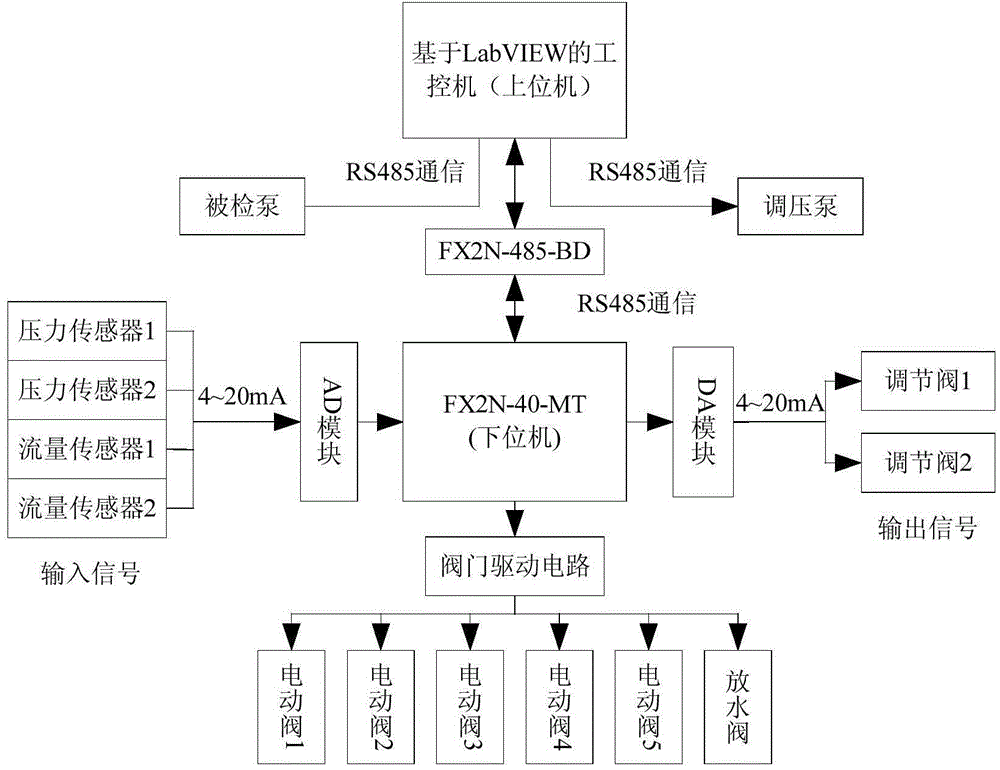
[0019] The present invention is an automatic test system for water pump performance detection, which is configured as follows:

[0020] serial number device name Specification quantity unit Remark 1 PLC FX2N-40MT 1 tower 2 Analog input module FX2N-4AD 1 indivual Each module contains 4 inputs 3 Analog output module FX2N-4DA 1 indivual Each module contains 4 outputs 4 driver module Valve drive circuit 1 indivual Each module contains 8 channels 5 switching power supply DC24 V 2A output 2 indivual For DA module and AD module and drive circuit 6 transformer AC220 V Turn to AC24 V 1 indivual 7 communication hardware FX2N-485-BD 1 indivual 8 programming software LabVIEW 1 set

[0021] Further illustrate the present invention below in conjunction with accompanying drawing.

[0022] refer to figure 1 As shown, the system consists of three parts, ...


PUM


Abstract

The invention relates to a water pump automatic test system. The test system adopts three detecting modes such as constant voltage, constant current and proportion, and an inlet pressure value which flows into a detected pump is changed through controlling pressure regulating pump frequency to achieve a water pump performance test under different inlet pressure conditions. The inlet pressure value, an outlet pressure value and a flow value of the detected pump is measured by a pressure sensor and a flow sensor, according to an energy equation, the size of a lift of the detected pump is obtained, and the relation between the lift and the flow is obtained at the same time. A control section adopts an industrial control computer and a PLC, a collection, an analysis and a treatment of detecting device data are achieved, and an open degree of an adjusting valve and start-up and shut-down of a switching valve are controlled simultaneously. By the adoption of the test system, an automatic test of the water pump on the ways of the constant voltage, the constant current and the proportion can be achieved, the test precision and the test efficiency of water pump parameter are improved, and the cost of the system is reduced.

Description

technical field [0001] The invention belongs to the technical field of automatic control, and relates to an automatic test system for water pumps. Background technique [0002] Water pumps are widely used in industry, agriculture, national defense construction and other fields, especially in the industrial field. The performance of water pumps directly affects the production process, production efficiency and production safety. Therefore, it is important to test water pumps. significance. [0003] In some developed countries abroad, such as the United States and the United Kingdom, the research on water pump testing started earlier, and the use of computer-aided performance testing systems for water pumps is more common, and its testing accuracy and automation are higher. These countries have relatively advanced water pump performance testing and processing technology, and the water pump performance testing system has the characteristics of high integration, com...

Claims


Application Information

Patent Timeline
Patent Type & Authority Applications(China)
IPC IPC(8): F04B51/00
Inventor 赵伟国周浩杰廉晨龙朱家顺高科
Owner CHINA JILIANG UNIV
Why Eureka
Try Eureka