
Plunger pump valve plate with local micro unit structures

A valve plate, unit body technology, applied in pump control, pump components, variable capacity pump components, etc., can solve problems such as failure to solve eccentric wear, narrow application area, increased cost, etc., to achieve a wide range of use, eccentric load The effect of less wear and longer service life

Inactive Publication Date: 2015-05-06
WUHAN UNIV OF SCI & TECH
View PDF7 Cites 2 Cited by
  • Summary
  • Abstract
  • Description
  • Claims
  • Application Information

AI Technical Summary

Problems solved by technology

[0005] To sum up, the existing technology has the following problems in the treatment of the distribution plate: increased cost, complex structure, narrow applicable surface, and failure to solve the problem of eccentric wear

Method used


Image

  • Plunger pump valve plate with local micro unit structures
  • Plunger pump valve plate with local micro unit structures
  • Plunger pump valve plate with local micro unit structures

Examples


Embodiment 1

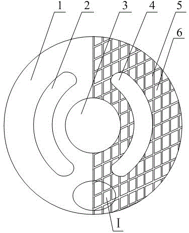
[0022] A plunger pump with a local micro unit structure.like figure 1 It is shown that the stream disk is equipped with a central hole 3, the center -to -hole 3 is equipped with oil windows 2, the other side of the center Tongkou 3 is equipped with oil -absorbing window 4, oil windows 2 and oil absorption window 4 are all are all are all"C" shaped pores, oil windows 2 and oil -absorbing window 4 The diameter lines of the stream disk are symmetrically distributed along the stream disk. A diameter lines are divided into two semi -circular dial surfaces of equal area.

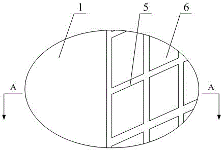
[0023] The semi -circular stream disk surface where the oil windows 2 are located is the oil stream disk surface 1, and the other semi -circular stream disk of the oil absorption window 4 is 5.like figure 1 and figure 2 Show, there are density distribution such as micro unit body structure 6 and microfinance structure 6 in the oil absorption dishes 5.

[0024] The structure of the micro unit body 6 is a miniature conv...

Embodiment 2

[0026] A plunger pump with a local micro unit structure.Except for the following structure, the rest are the same as 1.

[0027] There are density distribution such as micro unit body structure 6 and microfinance structure 6 in the oil absorption dishes 5.

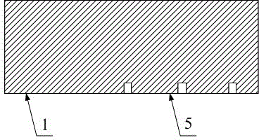
[0028] The structure of the micro unit body 6 is a miniature convex, and the upper surface shape of the micro conveye is a triangle, round, polygon, and oval.The area of the distribution disk is 50 ~ 80%, and the shape distance of the two adjacent micro convectors is 10-60 μm.5-50 μm.

[0029] Compared with the existing technology, this specific implementation method has the following advantages:

[0030] 1. This specific embodiment is only set with a microstrobine structure 6 in any half of the circular distribution disk. It does not require other regulatory devices. The work is safe and reliable, simple structure and low cost.

[0031] 2. This specific implementation method has a microfinance structure 6 in any half of the...


PUM


Abstract

The invention relates to a plunger valve plate with local micro unit structures. According to the technical scheme, an oil-pressing window (2) and an oil-sucking window (4) are distributed symmetrically along one diameter line of the valve plate; the surface of the valve plate is partitioned into two semi-circular valve plate surfaces of equal areas by the diameter line; any semicircular valve plate surface is provided with the micro unit structures (6); the micro unit structures (6) are distributed at equal density; the micro unit structures (6) are micro bosses; the upper surfaces of the micro bosses are triangular, quadrangular, circular, polygonal and oval; the sum of the upper surface areas of the micro bosses is 50-90 percent of the semicircular valve plate surface area; the center distance between two adjacent micro bosses is 6-60 microns; the upper surfaces of the micro bosses are the same planes as the other semicircular valve plate surface; each micro boss is 5-50 microns in height. The plunger pump valve plate has the advantages of low cost, simple structure, wide application range, low unbalance loading wear and long service life.

Description

Technical field [0001] The present invention belongs to the field of plunger pumps with streamlined technology.Specifically involves a plunger pump with a local micrometer structure. Background technique [0002] The plunger pump is one of the most important hydraulic originals, and is widely used in fields such as construction machinery and aerospace.In the actual application of the plunger pump, it is found that the pressure distribution at both ends of the stream disk is uneven, which will generate a partial load torque, causing partial grinding on the surface of the stream disk, and reducing the service life of the distribution disc.With the development of science and technology, the plunger pump develops towards the direction of high pressure, high speed and large flow, and puts forward higher requirements for the performance of the plunger pump.Significance. [0003] The patented technology of "high -voltage large displacement oblique axial shaft congestion pump" (CN2007201...

Claims


Application Information

Patent Timeline
Patent Type & Authority Applications(China)
IPC IPC(8): F04B53/00F04B53/18F04B49/00
Inventor 毛阳曾良才余广卢艳蒋俊
Owner WUHAN UNIV OF SCI & TECH
Learn More