
Time-resolved charged particle imaging apparatus

A charged particle, time-resolved technology, applied in measuring devices, analyzing materials, material analysis through electromagnetic means, etc., can solve problems such as unsatisfactory detection and direct detection

Inactive Publication Date: 2015-05-06
DALIAN INST OF CHEM PHYSICS CHINESE ACAD OF SCI
View PDF5 Cites 12 Cited by
  • Summary
  • Abstract
  • Description
  • Claims
  • Application Information

AI Technical Summary

Problems solved by technology

[0005] Although the above-mentioned experimental methods and means have been proved to be able to obtain very good excited state information, the dynamic process shown by the excited state, such as the process of internal conversion and intersystem crossing in the excited state, cannot be directly analyzed. detection of
In addition, the above-mentioned excited state processes mostly occur on ultrafast time scales (about 10 -15 Wonderful), conventional detection methods can no longer satisfy the detection of the above process

Method used


Image

  • Time-resolved charged particle imaging apparatus
  • Time-resolved charged particle imaging apparatus
  • Time-resolved charged particle imaging apparatus

Examples


Embodiment 1

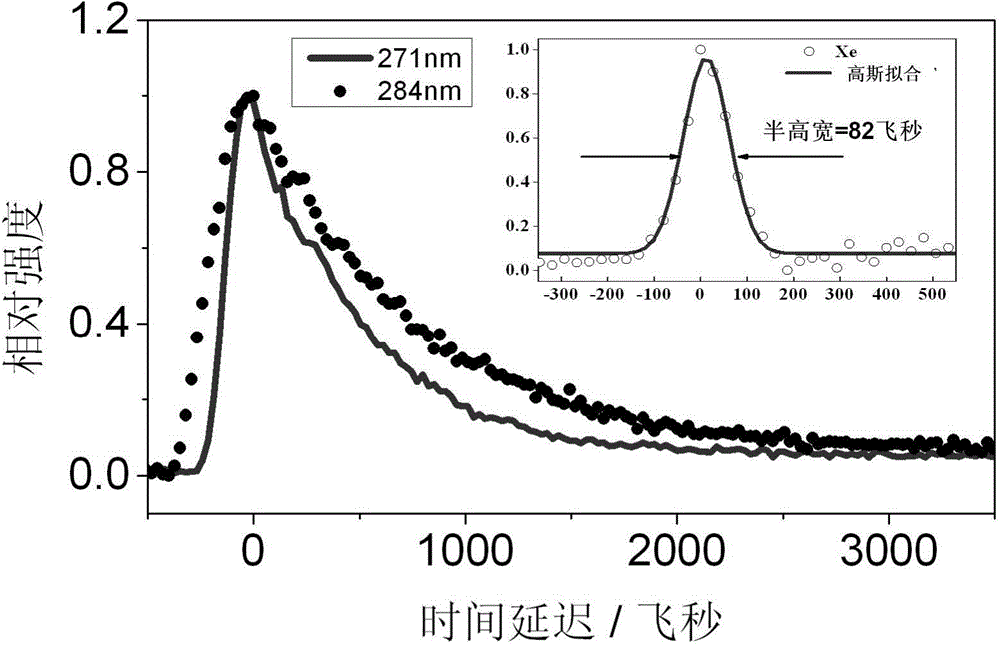
[0042] Time-resolved measurement of ultrafast decay kinetics of benzaldehyde

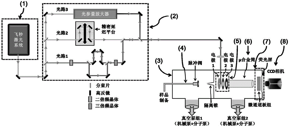
[0043] The test in this embodiment is used to illustrate the time-resolved characteristics of the time-resolved charged particle imaging device. First, using helium as a carrier gas, it is passed into the analytically pure benzaldehyde liquid to form a mixed gas mixed with benzaldehyde molecules. The mixed gas flows through the pulse valve, and is injected into the first-stage vacuum chamber through ultrasonic diffusion to form ultrasonic molecular beams. The molecular beam is collimated through the isolation cone, so that the ultrasonic molecular beam with a single direction is obtained in the second-stage vacuum cavity.

[0044] In this embodiment, the laser wavelength output by the femtosecond laser system 1 is 810 nanometers, and a time-resolved optical path can be formed by the delay optical path system 2 . Specific to this embodiment, firstly, the optical path 1 and the optical path 2 in the...

Embodiment 2

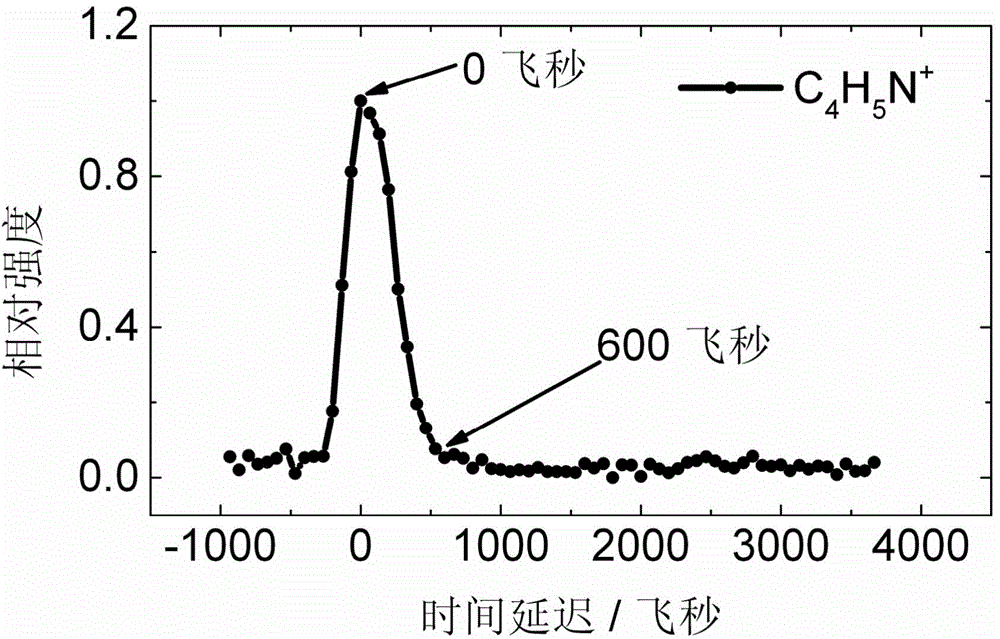
[0047] Time-resolved photoelectron images of pyrrole

[0048] The purpose of the test in this embodiment is to illustrate another characteristic of the present invention, that is, the time-resolved photoelectron image of the electronically excited state of a molecule can be directly measured. First, using helium as a carrier gas, it is passed into the analytically pure pyrrole liquid to form a mixed gas mixed with pyrrole molecules. The mixed gas flows through the pulse valve, and is injected into the first-stage vacuum chamber through ultrasonic diffusion to form ultrasonic molecular beams. The molecular beam is collimated through the isolation cone, so that the ultrasonic molecular beam with a single direction is obtained in the second-stage vacuum chamber. The laser wavelength output by the femtosecond laser system 1 is 810 nanometers, and a time-resolved optical path can be formed through the delay optical path system 2 . Specifically in this embodiment, firstly, the opt...


PUM

PropertyMeasurementUnit
Spectral widthaaaaaaaaaa
Outer diameteraaaaaaaaaa
Diameteraaaaaaaaaa

Abstract

The invention relates to a time-resolved charged particle imaging apparatus. The apparatus includes a femtosecond laser system, delay light path system, a vacuum system, a beam source system, a charged particle velocity focusing electrode group, an external magnetic field shielding system, a charged particle imaging detector and an image acquisition system. The apparatus combines a femtosecond ultrafast time resolution technology with a charged particle velocity focusing and imaging technology, and can be used to measure the high resolution energy spectrum of charged particles of high resolution and the real-time change information of angle distribution in order to realize detection of the ultrafast dynamics process of the excited state of a neutral atom or molecule system. The development of an experiment method with an ultrafast time resolution function is important in order to obtain detailed dynamics information of the excited state of atoms and molecules.

Description

technical field [0001] The invention relates to the field of microscopic chemical reaction kinetics, in particular to a time-resolved charged particle imaging device for detecting the ultrafast kinetic process of molecular excited states, which can realize the ultrafast kinetics of electronically excited states of neutral molecular systems Real-time detection of information. Background technique [0002] The main purpose of microscopic chemical reaction kinetics is to reveal how the chemical reaction process proceeds at the atomic and molecular level. In order to achieve the above purpose, many specific experimental methods and techniques have been developed to detect the total reaction interface, the velocity and angle distribution of the product, the quantum state distribution of the product, the product angle The orientation and orientation of the momentum and the orientation and orientation of the reactants affect the reaction and so on. Specifically, the purpose of th...

Claims


Application Information

Patent Timeline
IPC IPC(8): G01N27/64
Inventor 刘本康王利王艳秋
Owner DALIAN INST OF CHEM PHYSICS CHINESE ACAD OF SCI
Learn More