Fully-automatic drill electric-discharge machine
A fine-hole electric discharge machine, fully automatic technology, applied in the direction of electric processing equipment, metal processing equipment, accessory devices, etc., can solve the problems of low processing yield, low degree of automation, and inability to judge whether the hole is opened, etc., to improve The effect of processing yield, reducing labor cost and high drilling efficiency
- Summary
- Abstract
- Description
- Claims
- Application Information
AI Technical Summary
Problems solved by technology
Method used
Image

Examples
Embodiment Construction
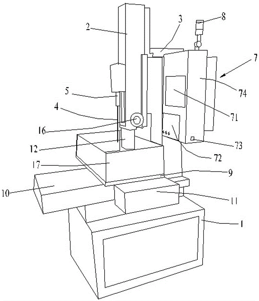
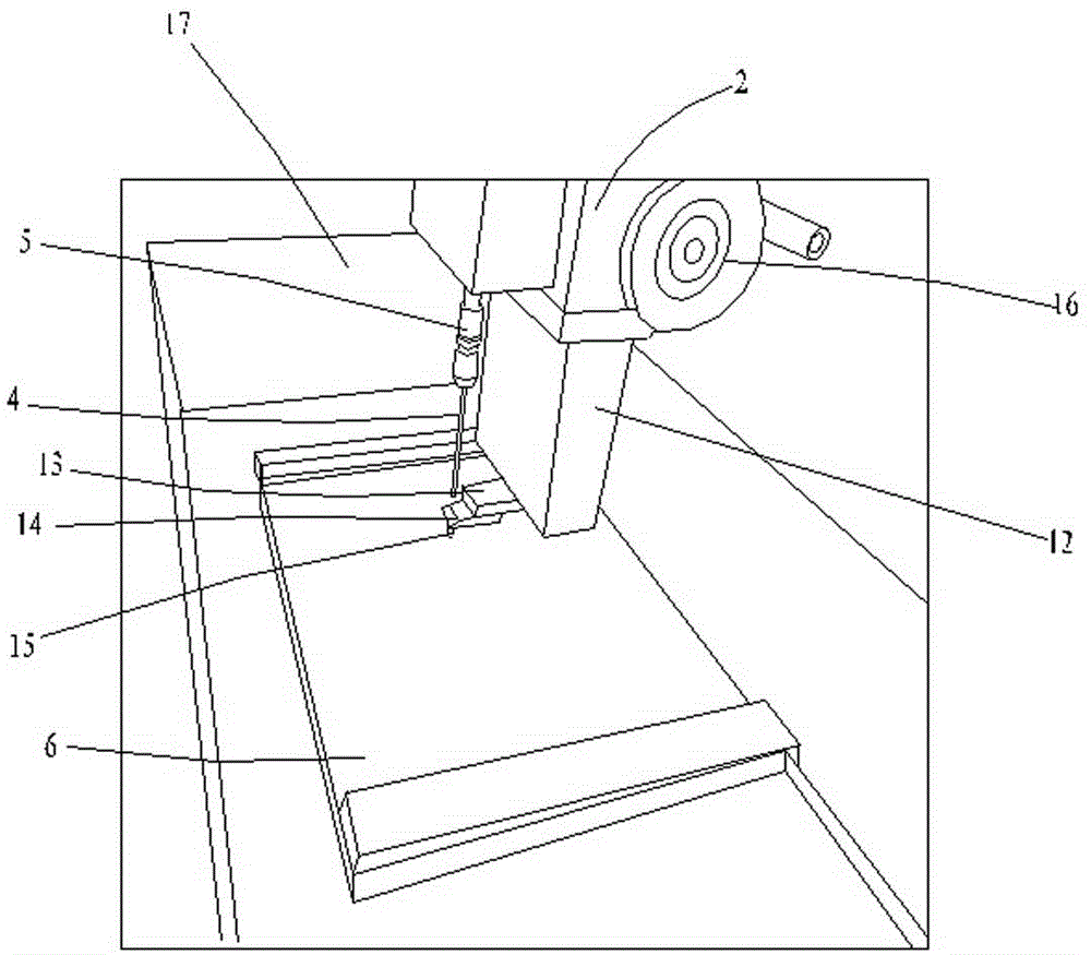
[0021] Such as figure 1 and figure 2 As shown, the present invention provides a fully automatic fine-hole discharge machine, including a frame 1, a lifting plate 2, a positioning bracket 3, an electrode wire 4, a rotating head 5, a driving device and a control system 7, and the lifting plate 2 is arranged on a positioning On the bracket 3, the positioning bracket 3 is arranged on the frame 1, the rotating head 5 is connected with the lifting plate 2, and the rotating head 5 is connected with a driving device, the driving device is a servo motor, and the driving device can drive the rotating head 5 to rotate.
[0022] The electrode wire 4 is fixed on the rotating head 5 and extends toward the frame 1. The rotation of the rotating head 5 can drive the electrode wire 4 to rotate together, so that the electrode wire 4 contacts the workpiece to be processed, and the metal is etched by pulse spark discharge. Holes are thus formed on the workpiece to be machined. The electrode wir...
PUM
 Abstract
Description
Claims
Application Information