
Gas production simulation system

A simulation system and gas extraction technology, applied in simulators, mining fluids, teaching models, etc., can solve the problems of expensive equipment, poor learning effect of students, and training on-site, so as to achieve low purchase and use costs, and equipment Easy layout and improved training efficiency

Active Publication Date: 2017-11-24
SOUTHWEST PETROLEUM UNIV +1
View PDF5 Cites 0 Cited by
  • Summary
  • Abstract
  • Description
  • Claims
  • Application Information

AI Technical Summary

Problems solved by technology

However, since almost all drilling sites and facilities are distributed in the wild, it is impossible to carry out training on site. If only relying on conventional classroom teaching or laboratory operations, due to the lack of vivid, intuitive and vivid auxiliary means and methods, it is inevitable to fall into the The embarrassing situation that the course content is simple and boring, and the learning effect of the students is poor, and the training is difficult to achieve the expected effect
[0004] The traditional gas production simulation training uses real equipment for training, and the internal air is used as the medium to simulate the flow of natural gas. The traditional simulation training is a pressurized equipment, which has potential safety hazards. There is fluid inside, and the system is expensive to maintain and easy to damage. The data of pressure, temperature and flow are very different from those on site, unable to reflect the working conditions on site, the training effect is poor, the airtightness requirements are high, the equipment is expensive, and there are certain requirements for equipment materials, usually only standard parts can be used, and it is difficult to simulate leakage , blockage, valve damage, freezing and other accidents, all equipment must be physically connected, which makes the equipment layout more difficult and covers a large area

Method used


Image

  • Gas production simulation system
  • Gas production simulation system
  • Gas production simulation system

Examples


Embodiment Construction

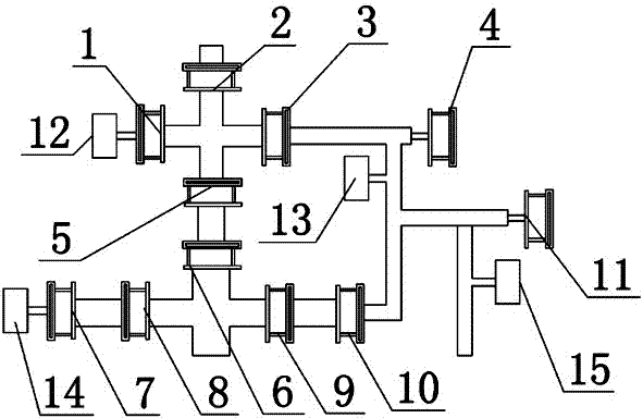
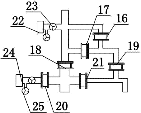
[0021] The technical solution of the present invention will be further described in detail below in conjunction with the accompanying drawings, but the protection scope of the present invention is not limited to the following description.

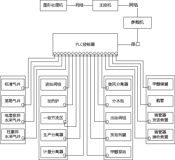
[0022] Such as figure 1 As shown, the gas production simulation system includes a gas production simulation device, a PLC controller and a control unit. The control unit includes a main control machine, a parameter machine and a graphics processor. The gas production simulation device is connected with the PLC controller, and the PLC The controller is connected to the parameter machine through the serial port, and the parameter machine and the graphic processor are respectively connected to the main control machine through the communication network;

[0023] The gas production simulation device is provided with a valve, a display meter, and a switch according to the actual gas production equipment, and the PLC controller is provided with a ...


PUM


Abstract

The invention discloses a gas production simulation system which comprises a gas production simulation device, a PLC and a control unit. The control unit comprises a master control computer, a parameter machine and a graphic processor, the gas production simulation device is connected with the PLC, the PLC is connected with the parameter machine through a serial port, and the parameter machine and the graphic processor are connected with the master control computer through a communication network. According to the gas production simulation system, no real fluid exists in equipment of the system, all operable parts of the equipment are provided with sensors, the sensors collect the opening degrees, opening and closing states and other information of valves and transmit the opening degrees, the opening and closing states and the other information to the master control computer, the master control computer calculates flowing conditions and pressure conditions in current pipelines according to a mathematic model, the conditions are displayed in a large screen, and pressure data are sent to all display meters. No medium exists in all operating devices, the operating devices have no pressure, safety and stability are achieved, the whole operating process is highly consistent with the field, and training quality and training efficiency are improved.

Description

technical field [0001] The invention relates to the field of oil drilling training, in particular to a gas production simulation system. Background technique [0002] Petroleum and oil fields often store natural gas resources in addition to oil, so natural gas must be exploited in the process of oil exploitation. Gas extraction engineering is a dominant system engineering in natural gas extraction engineering. Yield development plays a pivotal role. [0003] However, for new oilfield employees or students majoring in oil and gas related majors, they have no perceptual understanding of gas recovery processes, separators, heating furnaces and other equipment, or handling methods in case of accidents, and are not familiar with on-site gas recovery operations. Once there is an operation error or carelessness, it may cause serious quality accidents or safety accidents, which will bring great losses to the country and the people. Therefore, the on-the-job knowledge training and ...

Claims


Application Information

Patent Timeline
Patent Type & Authority Patents(China)
IPC IPC(8): E21B43/00
CPCG09B9/00G09B25/02
Inventor 龚捷王世元
Owner SOUTHWEST PETROLEUM UNIV
Learn More