

Hydraulic type energy recovery system for potential energy of boom of excavator
An energy recovery, hydraulic technology, applied in the direction of fluid pressure actuation system components, mechanical equipment, actuator accumulators, etc., can solve the problem of unstable outlet pressure, long response time for variable pump outlet pressure establishment, and difference in operating performance, etc. problem, to achieve the effect of improving recycling efficiency
- Summary
- Abstract
- Description
- Claims
- Application Information
AI Technical Summary
Problems solved by technology
Method used
Image


Examples
Embodiment Construction
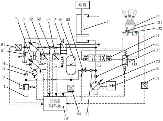
[0027] see Figure 1 to Figure 3 As shown, the excavator arm potential energy hydraulic energy recovery system includes a variable motor 8, two variable pumps 71, 72, an accumulator 10, control valves 2, 31, 32, 33, 51, 52, 53, 9, 131, 132, 14, 15, ECU control unit 18, pressure sensors 61, 62, 63, 64 speed sensor 4, hydraulic cylinder 11, fuel tank 1, engine 16;
[0028] The variable motor 8 is coaxially installed with the first variable pump 71 and the rotational speed sensor 4, the inlet of the variable motor 8 is connected in series with the throttle valve 52, and the other end of the variable motor 8 is divided into two ways to connect the throttle valve 51 and the reversing valve 9 respectively; the throttle valve 52 The other end is connected to the reversing valve 9, and the two working oil chambers of the reversing valve 9 are respectively connected to the upper and lower chambers of the hydraulic cylinder 11; the inlet of the variable pump 71 is connected to the oil t...
PUM
 Abstract
Description
Claims
Application Information