Imaging device based on fly-eye lens optical structure and imaging method thereof

A fly-eye lens and optical structure technology, applied in optics, lenses, optical components, etc., can solve problems such as limited image information, complex manufacturing process, and increased difficulty in system implementation, achieving the effect of high-performance photoelectric imaging

Inactive Publication Date: 2015-05-13
HANGZHOU QINGQU TECH
View PDF5 Cites 3 Cited by
  • Summary
  • Abstract
  • Description
  • Claims
  • Application Information

AI Technical Summary

Problems solved by technology

Although this prior art has certain advantages, there are still essential deficiencies: 1) this method comprises the fly-eye lens facing the object side and the fly-eye lens facing the image side, there are two groups of fly-eye lenses, and these two groups of fly-eye lenses will be coaxial , so the manufacturing process is complex, the photoelectric structure is complex, and the system is difficult to realize; 2) During the construction process, the opening diameter of the lens units in the fly-eye lens is required to be consistent, and the back focal lengt...

Method used


Image

  • Imaging device based on fly-eye lens optical structure and imaging method thereof
  • Imaging device based on fly-eye lens optical structure and imaging method thereof

Examples


Embodiment Construction

[0024] The present invention will be described in further detail below in conjunction with the accompanying drawings.

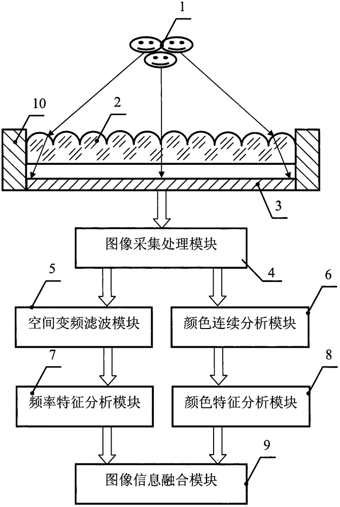
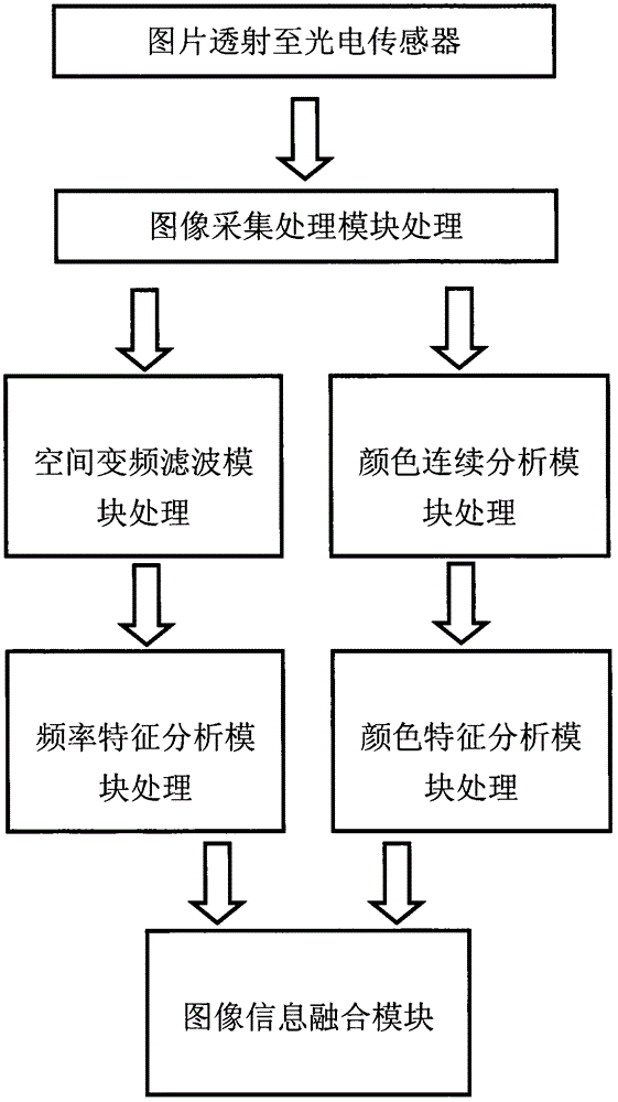
[0025] Such as figure 1 Shown is a schematic structural diagram of an imaging device based on the optical structure of a fly-eye lens according to an embodiment of the present invention. The specific embodiments are as follows: an imaging device based on an optical structure of a fly-eye lens includes an image light source 1 and sequentially arranged along the light source beam outgoing direction The fly-eye lens 2 and the photoelectric sensor 3, the photoelectric sensor 3 is connected with the image acquisition and processing module 4, the image acquisition and processing module 4 is connected with the space frequency conversion filter module 5 and the color continuous analysis module 6, and the space frequency conversion filter module 5 is connected with the frequency special increase analysis The module 7 and the color continuous analysis module 6 are conn...


PUM


Abstract

The invention discloses an imaging device and method based on the fly-eye lens optical structure. The fly-eye lens imaging principle based on bionics is combined with a variable space frequency characteristic extraction technology, an image of the object space is formed on the plane of a two-dimensional photoelectric sensor through a fly-eye lens, image processing is conducted through a space frequency conversion filtering module and a color continuous analysis module, then image information blending is conducted, and required image characteristics and images are output to achieve high performance photoelectric imaging. The imaging method is simple in photoelectric structure, easy to achieve, low in mechanical requirement, flexible in system construction, prone to extract and analyze characteristic information, high in data processing capability and prone to integration and function expansion.

Description

technical field [0001] The invention belongs to the field of optical technology, and relates to an imaging device and an imaging method thereof, in particular to an imaging device and an imaging method based on a compound eye optical structure, which are mainly used in artificial intelligence, robots, mobile terminals, photoelectric imaging, photoelectric detection, material Imaging in the fields of analysis, optical lighting, projection technology, optical microscopy, optical manipulation, optical communication, artificial intelligence, robotics, mobile terminals, Internet of Things, environmental perception, guidance and navigation, and cultural relics protection. Background technique [0002] Imaging widely exists in the fields of mobile terminals, robots, photoelectric systems, photoelectric detection, material analysis, optical lighting, projection technology, optical microscopy, optical manipulation, optical communication, artificial intelligence, Internet of Things, en...

Claims


Application Information

Patent Timeline
IPC IPC(8): G02B27/00G02B3/00H04N5/225
CPCG02B27/00G02B3/005H04N23/55
Inventor 樊兆华黄灏高秀敏
Owner HANGZHOU QINGQU TECH
Why Eureka
Try Eureka