
Transformer

A transformer and a technology, applied in the field of transformers, can solve the problems of low efficiency, increased loss, and large leakage inductance of transformers, and achieve the effects of reducing leakage inductance, improving efficiency, and reducing loss and voltage loss.

Inactive Publication Date: 2015-05-13
SHENZHEN DBK ELECTRONICS
View PDF5 Cites 7 Cited by
  • Summary
  • Abstract
  • Description
  • Claims
  • Application Information

AI Technical Summary

Problems solved by technology

[0011] It can be seen from the above formula that the leakage inductance of the traditional winding process is relatively large, and the efficiency of the transformer is relatively low
Moreover, in order to reduce the increase of high-frequency AC impedance caused by the skin effect, the secondary generally uses Litz wire, which is composed of multiple thin wires, which are easy to break during operation and often cause increased loss.

Method used


Image

  • Transformer
  • Transformer

Examples


Embodiment Construction

[0023] In order to make the technical problems solved by the present invention, the technical solutions adopted, and the technical effects obtained easy to understand, the specific implementation manners of the present invention will be further described below in conjunction with the specific drawings.

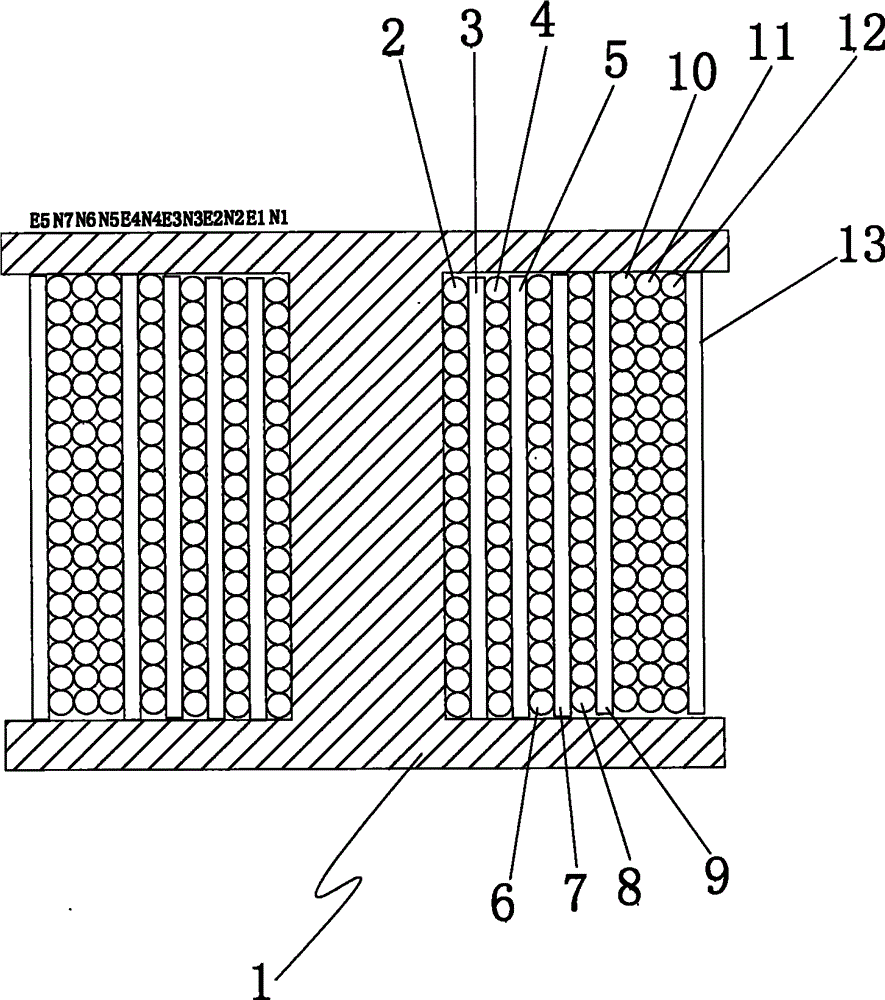
[0024] refer to figure 1 , The present invention provides a transformer, including a skeleton 2, a secondary coil and a primary coil wound on the skeleton 2, and the cross section of the skeleton 2 is preferably "I"-shaped in the present invention.

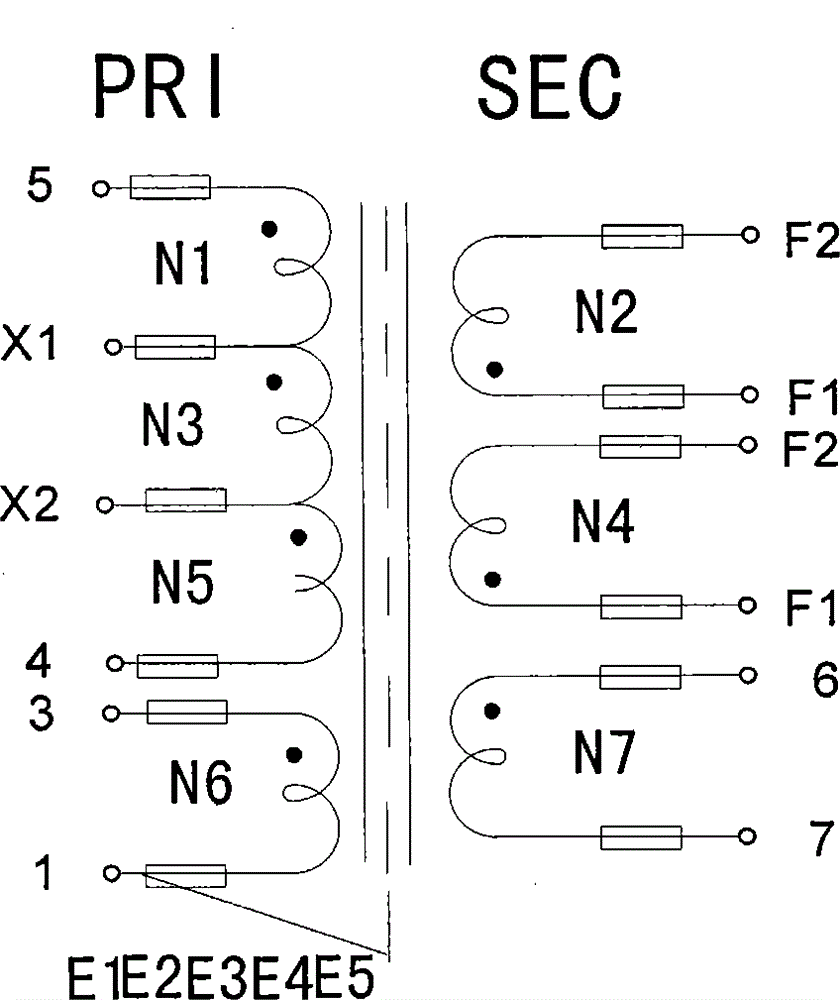
[0025] A layer of first coil (N1) 2 as a primary coil, a layer of second coil (N2) 4 as a secondary coil, and a layer of third coil (N3) as a primary coil are wound along the axial direction of the skeleton 2 6. One layer of fourth coil (N4) 8 as the secondary coil, one layer of fifth coil (N5) 10 as the primary coil. That is to say, the first coil 2 , the second coil 4 , the third coil 6 , the fourth coil 8 and the fifth coil 10...


PUM

PropertyMeasurementUnit
diameteraaaaaaaaaa

Abstract

The invention discloses a transformer. A layer of first coil serving as a primary coil, a layer of second coil serving as a secondary coil, a layer of third coil serving as a primary coil, a layer of fourth coil serving as a secondary coil and a layer of fifth coil serving as a primary coil are wound in the axial direction of a framework, and shielding layers are arranged between the first coil and the second coil, between the second coil and the third coil, between the third coil and the fourth coil and between the fourth coil and the fifth coil respectively. According to the transformer, the winding structure of the primary coil, the secondary coil, another primary coil, another secondary coil and another primary coil is adopted, gaps between the primary coils and the secondary coils are greatly reduced, and leakage inductance is greatly reduced. Meanwhile, total magnetic field intensity of the gaps between the primary coils and the secondary coils is lowered, the total energy of a primary winding space magnetic field and the total energy of a secondary space magnetic field are greatly reduced, and leakage inductance is further reduced and is almost 2-4% of primary inductance. Due to the fact that the leakage inductance is reduced, loss of the transformer and voltage loss are greatly reduced.

Description

technical field [0001] The invention belongs to the field of transformers, and more precisely relates to a transformer with small leakage inductance. Background technique [0002] A transformer is a component for energy transfer, conversion, storage, and release. It can be used for AC input and DC output flyback topology power conversion. It is widely used in the power supply of electronic consumer products for voltage conversion, safety isolation, storage and emit energy. The transformer will work in DCM (discontinuous), CRM (critical continuous), and CCM (completely continuous) modes. The middle column of the magnetic core needs to grind the air gap to support the DC magnetic flux caused by the large DC magnetizing current, and the BH hysteresis The slope of the loop becomes smaller, and due to the existence of the air gap, energy is stored in the air gap (reluctance), which reduces the residual magnetic flux density and increases the range of the AC magnetic flux density...

Claims


Application Information

Patent Timeline
Patent Type & Authority Applications(China)
IPC IPC(8): H01F27/28H01F27/36
Inventor 曾金辉
Owner SHENZHEN DBK ELECTRONICS
Learn More