Energy-saving control circuit based on switch sequence control and rlc oscillation to generate magnetic field

A technology of switching timing and energy-saving control, which is applied in the direction of electrical components, output power conversion devices, and conversion equipment that can be converted to DC without intermediate conversion, and can solve problems such as device heating

Active Publication Date: 2019-11-19
TIANJIN POLYTECHNIC UNIV
View PDF7 Cites 0 Cited by
  • Summary
  • Abstract
  • Description
  • Claims
  • Application Information

AI Technical Summary

Problems solved by technology

[0007] The invention provides an energy-saving device based on switch timing control and RLC oscillation to generate a magnetic field, which solves the problem of serious heat generation in traditional magnetic field generating devices

Method used


Image

  • Energy-saving control circuit based on switch sequence control and rlc oscillation to generate magnetic field
  • Energy-saving control circuit based on switch sequence control and rlc oscillation to generate magnetic field
  • Energy-saving control circuit based on switch sequence control and rlc oscillation to generate magnetic field

Examples


Embodiment 1

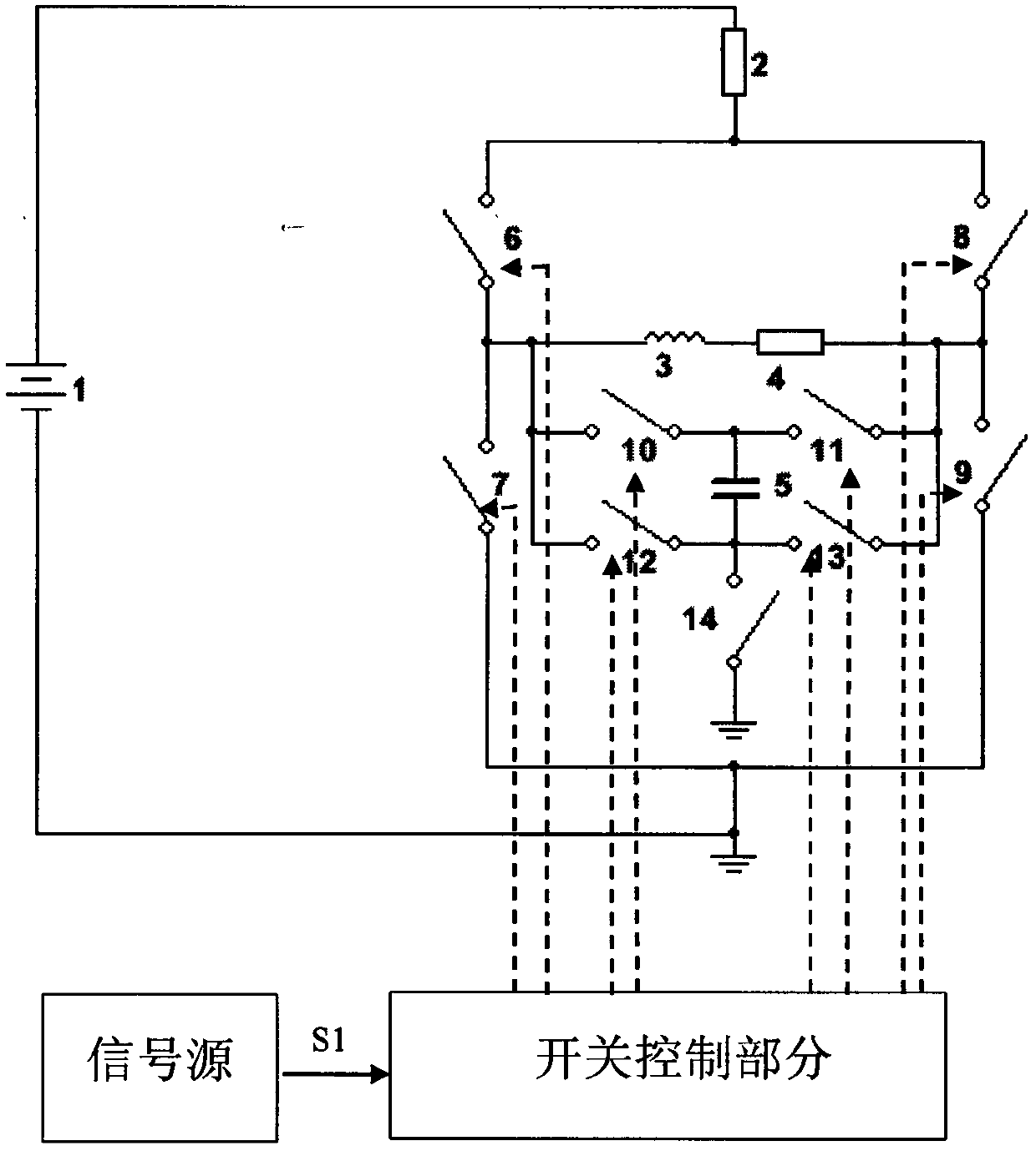
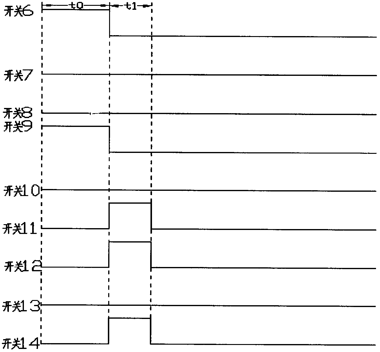
[0034] according to figure 1 and figure 2 As shown, after setting the resistance value of the adjustable resistor 2, the double H bridge circuit is energized, and the current direction after the coil 3 is energized is as follows: Figure 5 As shown, that is, the switches 6 and 9 of the double H bridge circuit are closed, the switches 7, 8, 10, 11, 12, 13, and 14 are opened, and the coil 3 is energized in this direction for t 0 Time produces a constant magnetic field; where t 0 should satisfy t 0 >5τ, because the inductor current only needs to go through 5τ (τ is the time constant of the RL circuit, its value is τ=L / R), it has exceeded 99% of the maximum value and tends to a steady state, so t is taken 0 >5τ, the current passing through the coil 3 reaches the maximum and has been stabilized.

[0035] Turn off the switches 6 and 9, close the switches 11, 12, and 14, and at the same time, keep the switches 7, 8, 10, and 13 in the off state. At this time, the impedance coils ...

Embodiment 2

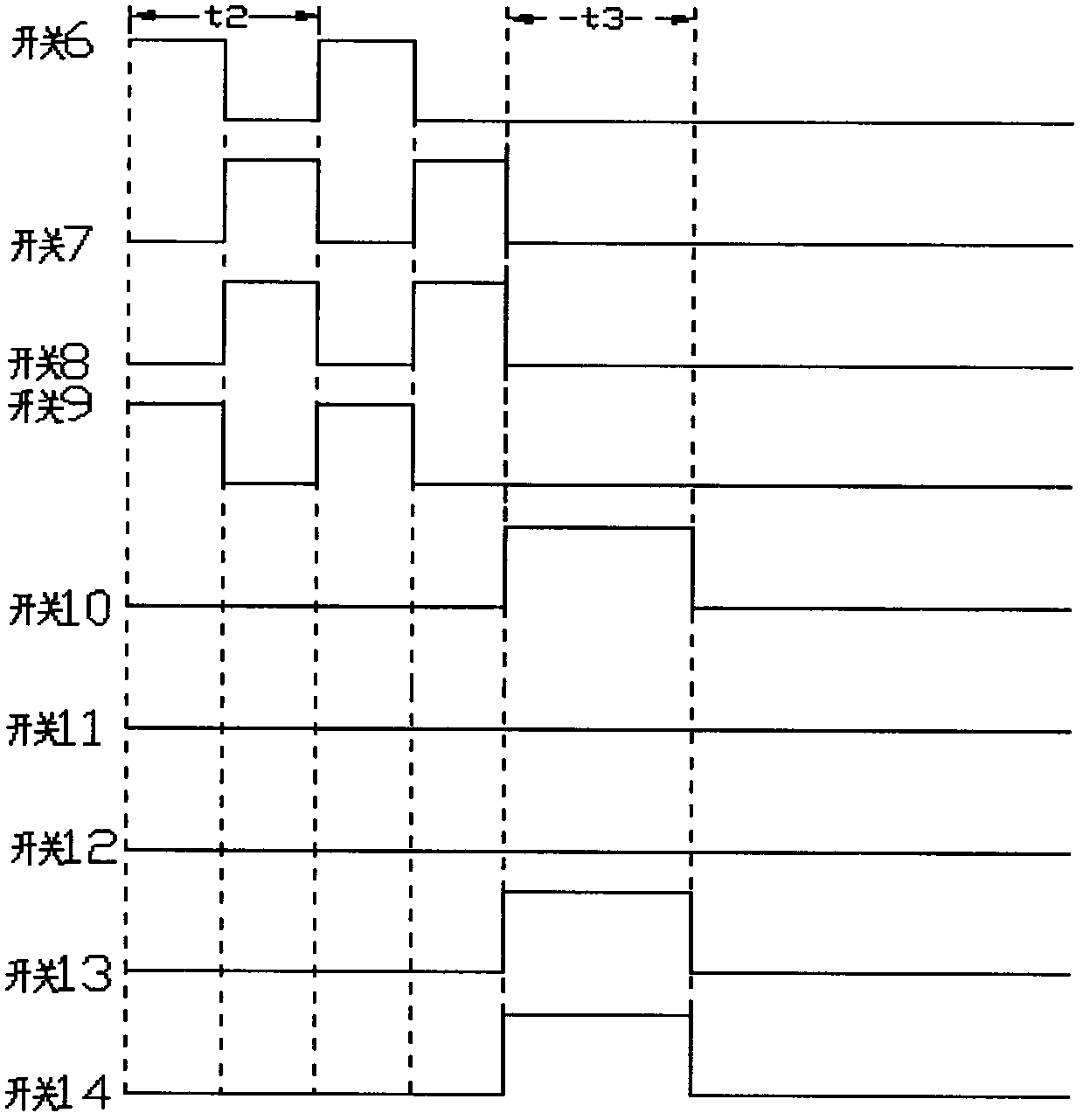
[0038] according to figure 1 and image 3 As shown, after setting the resistance value of the adjustable resistor 2, the double H bridge circuit is energized, the switches 10, 11, 12, 13, and 14 remain in the off state, and the switches 6, 9 and switches 7, 8 follow the time cycle t 2 Turn on and off alternately; when switches 6 and 9 are on and switches 7 and 8 are off, the current direction of coil 3 in the circuit is as follows: Figure 5 As shown; when the switches 7 and 8 are closed and the switches 6 and 9 are open, the direction of the coil current in the circuit is as follows Figure 7 shown; thus, the coil generates an alternating magnetic field.

[0039] When the coils 3 and 4 in the double H bridge circuit are de-energized, if the switches 7 and 8 are closed and the switches 6 and 9 are disconnected at the previous moment, then the switches 6, 7, 8, 9, 11 and 12 are disconnected, and the switches 10, 13 and 14 are closed. At this time, the impedance coils 3 and ...

Embodiment 3

[0042] according to figure 1 and Figure 4 As shown, in the double H-bridge circuit, the electric energy stored in the capacitor 5 can be released into the coil 3 through the RLC oscillation process to generate a magnetic field and be reused. After setting the resistance value of the adjustable resistor 2, the double H-bridge circuit is energized, and the switches 6, 7, 8, and 9 remain off; if the coil is conductive, the initial current should be as follows Figure 5As shown in the current direction, the discharge process of the capacitor 5 to the coil through RLC oscillation should be: the switches 11 and 12 are kept open, and the switches 10, 13, and 14 are closed. At this time, the impedance coils 3 and 4 and the capacitor 5 constitute an RLC oscillation circuit. , the capacitor 5 discharges the impedance coils 3 and 4, and the current direction of the RLC circuit is as follows Figure 9 As shown; when the discharge of the capacitor 5 is completed, that is, the current of...


PUM


Abstract

The invention discloses a switch sequential control and PLC oscillation producing magnetic field based energy-saving control circuit. The control circuit comprises an RLC oscillating circuit consisting of a power supply, double H-bridge circuits, a capacitor and a coil, a signal source portion and a switch control portion. Magnetic fields of different types are produced by adjusting current of the coil 3. The signal source synchronously controls ON / OFF combinations of switches 6-14 in the H-bridge circuits by producing a synchronizing signal S1, enable a direct-current power supply to form current waveform required by the coil 3, and accordingly the coil produces a corresponding magnetic field. The control circuit enables the current of the coil to reach current intensity for reaching magnetic field intensity within short time by using the direct-current power supply, and current utilization rate is improved. Energy released by the coil through switch sequential control and capacitor coil charging and discharging after outage is converted into electric energy to be stored in a capacitor for reutilization, and accordingly energy loss and coil heating caused by the fact that the energy released after coil outage is converted into heat energy are avoided.

Description

technical field [0001] The invention relates to an energy-saving magnetic field generation control circuit for generating a magnetic field, in particular to a method for generating a magnetic field based on switch sequence control and RLC oscillation energy saving. The signal generated by the signal source regularly controls the on-off state of the switch. The adjustable resistor adjusts the magnitude of the current passing through the load, and the double H-bridge circuit switches the direction of the current passing through the load. The RLC oscillation causes the energy released after the coil is de-energized to be converted into each other in the capacitor and the coil. Background technique [0002] With the development of science and technology, different types of magnetic fields have begun to be used in industrial testing, food preservation, medical care and other fields. Most of the traditional methods of generating alternating magnetic fields are coils loaded with ...

Claims


Application Information

Patent Timeline
Patent Type & Authority Patents(China)
IPC IPC(8): H02P13/00
Inventor 熊慧鹿文龙刘近贞
Owner TIANJIN POLYTECHNIC UNIV
Why Eureka
Try Eureka