LED driving circuit

An LED driver and circuit technology, applied in the direction of electric lamp circuit layout, electric light source, lighting device, etc., can solve the problems of human ear noise, long conduction time, low circuit operating frequency, etc., to avoid noise, improve efficiency, and reduce switching. The effect of loss

Active Publication Date: 2015-05-13
FREMONT MICRO DEVICES SHENZHEN LTD
View PDF4 Cites 1 Cited by
  • Summary
  • Abstract
  • Description
  • Claims
  • Application Information

AI Technical Summary

Problems solved by technology

[0008] 3. The conduction time is very long when the input voltage is low, so the operating frequency of the circuit is very low, and it may even be lower than 20KHz, so there is the possibility of human ear noise

Method used


Image

  • LED driving circuit
  • LED driving circuit
  • LED driving circuit

Examples


Embodiment Construction

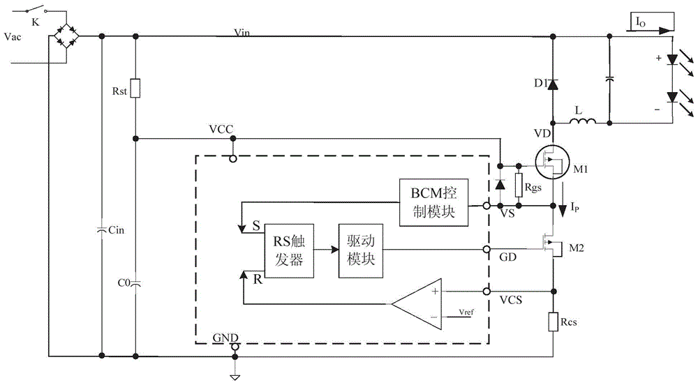
[0025] The invention aims at the problem that the conduction loss of the high-voltage MOS is increasing due to the voltage drop in the prior art; the minimum operating voltage of the circuit is high and the operating frequency of the circuit is too low when the input voltage is low, and there may even be human ear noise. An LED drive circuit adopts an automatic selection mode to make the circuit work in BCM mode at high input voltage to reduce switching loss; and automatically enters CCM mode at low input voltage, which can effectively improve efficiency at low voltage operation and reduce The minimum operating voltage is guaranteed, and noise can be avoided at the same time.

[0026] In order to have a clearer understanding of the technical features, purposes and effects of the present invention, the specific implementation manners of the present invention will now be described in detail with reference to the accompanying drawings.

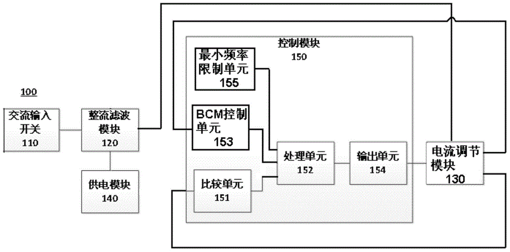
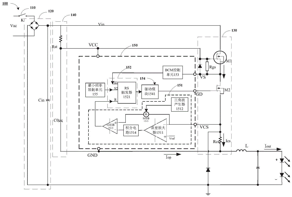
[0027] figure 2 It is a functional block...


PUM


Abstract

The invention provides an LED driving circuit. The LED driving circuit comprises an AC input switch (110), a rectifying filter module (120) of which the input end is connected with the AC input switch (110), a current regulating module (130) for providing constant current to a loaded LED, and a power supply module (140) of which the input end is connected with the rectifying filtering module (120); the output end of the rectifying filter module (120) is connected to the current regulating module (130). The LED driving circuit (100) further comprises a control module (150); the current regulating module (130) is used for sending a sampling signal to the control module (150); the power supply module (140) supplies working voltage to the control module (150). According to the LED driving circuit, the automatic selecting mode is adopted, thus the circuit can work in the BCM mode in case of high input voltage so as to reduce switch consumption, and the circuit automatically enters the CCM mode in case of low input voltage so as to effectively increase the efficiency of working at low voltage, and moreover, the minimum working voltage is reduced; meanwhile, noise can be avoided.

Description

technical field [0001] The present invention relates to the field of power electronics, and more specifically, relates to an LED driving circuit. Background technique [0002] The typical working principle of the prior art Buck constant current LED drive circuit is as follows: figure 1 As shown, the source of the high-voltage MOS is connected to the current detection resistor Rcs, and the gate of the MOS is fixedly connected to the VCC terminal. When the low-voltage MOS is turned on by the drive module, the node VS voltage will be pulled down, so that the high-voltage MOS is turned on. The current of the inductor will increase with a fixed slope, and the VCS voltage will also increase accordingly. When the inductor current increases to make VCS equal to the internal comparison voltage Vref of the controller, the drive module will turn off the low-voltage MOS, and the node VS will rise rapidly. When When VS rises to VCC-VS<Vth, the power switch M1 is turned off. At this t...

Claims


Application Information

Patent Timeline
IPC IPC(8): H05B37/02
CPCY02B20/40
Inventor 许如柏黄裕泉
Owner FREMONT MICRO DEVICES SHENZHEN LTD
Why Eureka
Try Eureka