
Ball mill with non-cylindrical inner cavity wall

A technology in the inner cavity wall and in the cylinder, which is applied in the direction of grain processing, etc., can solve the problems of no large-scale axial impact and grinding, less collision and friction between balls and raw materials, and large blindness of balls. Grinding effect, short ball milling cycle and low power consumption

Active Publication Date: 2015-05-20
毛新
View PDF6 Cites 4 Cited by
  • Summary
  • Abstract
  • Description
  • Claims
  • Application Information

AI Technical Summary

Problems solved by technology

[0004] Because the inner wall of the cylinder-shaped barrel of the traditional ball mill is a regular cylinder, the raw materials and ball stones are not subjected to axial force, and the grinding process is mainly carried out along the circumferential direction of the inner wall of the barrel, that is, radially, basically without large The range of axial impact and grinding results in fewer impacts and frictions between the ball stone and the raw material, greater blindness of the ball stone movement, lower ball milling efficiency and longer ball milling cycle; The large eccentric moment generated by the accumulation of ball stones and slurry at the bottom of the cylindrical cylinder will increase the power consumption and energy consumption of the motor to drive the cylindrical cylinder.

Method used


Image

  • Ball mill with non-cylindrical inner cavity wall
  • Ball mill with non-cylindrical inner cavity wall
  • Ball mill with non-cylindrical inner cavity wall

Examples


Embodiment Construction

[0019] In the following, the present invention will be further described in conjunction with the accompanying drawings and specific embodiments, so as to understand more clearly the technical idea claimed in the present invention.

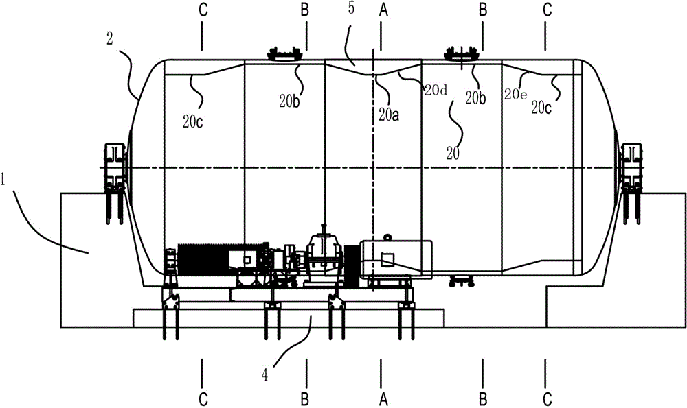
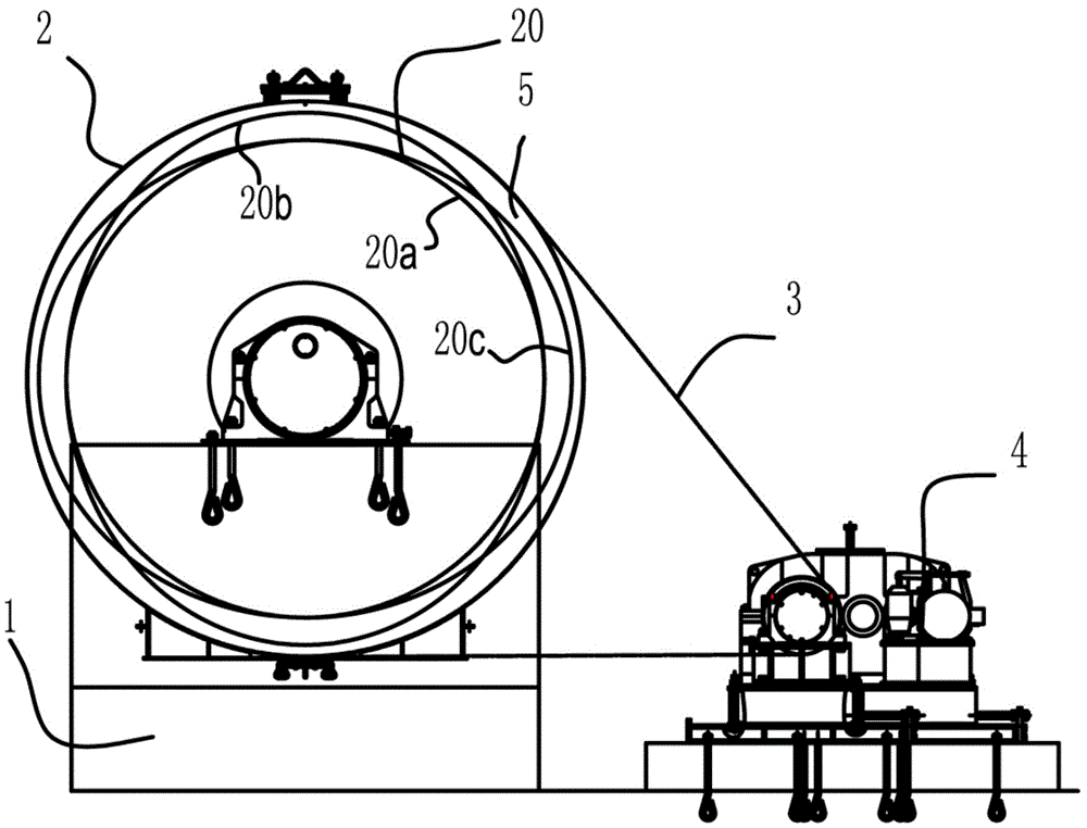
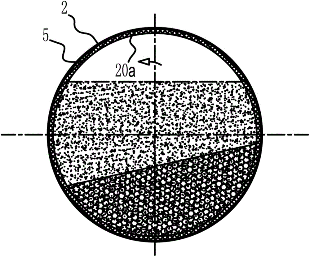
[0020] Such as Figure 1-5 The cylinder inner wall of the present invention shown is a non-cylindrical ball mill, comprising a frame 1, a cylinder 2, a transmission belt 3 and a driving device 4, the cylinder 2 is fixed on the frame 1 through a bearing, and the cylinder 2 passes through The transmission belt 3 is connected with the driving device 4 to realize the rotation of the cylindrical body 2 driven by the driving device 4 . The inner cavity of the cylinder body 2 is used to hold ball stones, raw materials, slurry, etc., and its inner cavity wall 20 is a segmented irregular shape, including a circular cross-section inner cavity wall 20a arranged in the middle of the cylinder body 2, symmetrically arranged The first elliptical section inner ca...


PUM


Abstract

The invention discloses a ball mill with a non-cylindrical inner cavity wall. The ball mill comprises a frame, a cylinder body, a transmission belt and a driving device, wherein the inner cavity wall of the cylinder body is in a sectional irregular shape; the inner cavity wall of the cylinder body comprises a circular-section inner cavity wall arranged in the middle of the cylinder body, first elliptical-section inner cavity walls symmetrically arranged at the two sides of the circular-section inner cavity wall and second elliptical-section inner cavity walls symmetrically arranged at one sides of the first elliptical-section inner cavity walls; the long shafts of the section ellipses of the first elliptical-section inner cavity walls and the second elliptical-section inner cavity walls are perpendicular to each other; a first irregular inner cavity wall and a second irregular inner cavity wall are orderly arranged between the circular-section inner cavity wall, the first elliptical-section inner cavity walls and the second elliptical-section inner cavity walls to form transitional linkages respectively; and the inner cavity wall of the cylinder body is a cylinder inner wall of the cylinder body or an inner wall of an irregular rubber lining installed on the cylinder inner wall of the cylinder body. The ball mill disclosed by the invention has advantages of high ball mill efficiency, short ball mill cycle and low energy consumption.

Description

technical field [0001] The invention relates to the technical field of grinding processing equipment, in particular to a ball mill. Background technique [0002] Ball mill is widely used in the production of ceramics, cement, silicate products, new building materials, refractory materials, fertilizers, non-ferrous metal beneficiation and glass to grind various ores and other grindable materials. . The barrel of the traditional ball mill is cylindrical, and the inner cavity of the cylindrical barrel is used for ball stones, grinding raw materials and slurry, etc., and the inner cavity wall is regular cylindrical. The ball mill is driven by a motor to rotate its cylinder-shaped barrel, so that the balls in the inner cavity of the barrel hit the raw materials to crush and grind the raw materials. The process of grinding the raw materials by the ball mill is divided into two stages. The first stage is that the balls follow the barrel. When the body moves and falls, it collid...

Claims


Application Information

Patent Timeline
IPC IPC(8): B02C17/22B02C17/24
CPCB02C17/10B02C17/22B02C17/225B02C17/24
Inventor 毛新陈晓松
Owner 毛新
Learn More