Device and method for controlling suspension welding seam root gap and welding deformation in self-supporting mode

A welding seam root, welding deformation technology, applied in auxiliary devices, welding equipment, welding equipment and other directions, can solve problems such as reducing production efficiency, and achieve the effects of improving production efficiency, strong adaptability, and significant positioning effect

Active Publication Date: 2015-05-20
CSSC HUANGPU WENCHONG SHIPBUILDING COMPANY
View PDF8 Cites 6 Cited by
  • Summary
  • Abstract
  • Description
  • Claims
  • Application Information

AI Technical Summary

Problems solved by technology

During the entire welding process, the production efficiency is greatly reduced due to additional processes such as spot welding, welding and removal of clips and angle aluminum, grinding and shaping of the back of the weld, and post-welding correction.

Method used


Image

  • Device and method for controlling suspension welding seam root gap and welding deformation in self-supporting mode
  • Device and method for controlling suspension welding seam root gap and welding deformation in self-supporting mode
  • Device and method for controlling suspension welding seam root gap and welding deformation in self-supporting mode

Examples


Embodiment 1

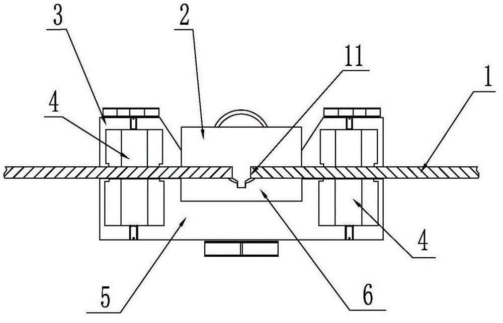
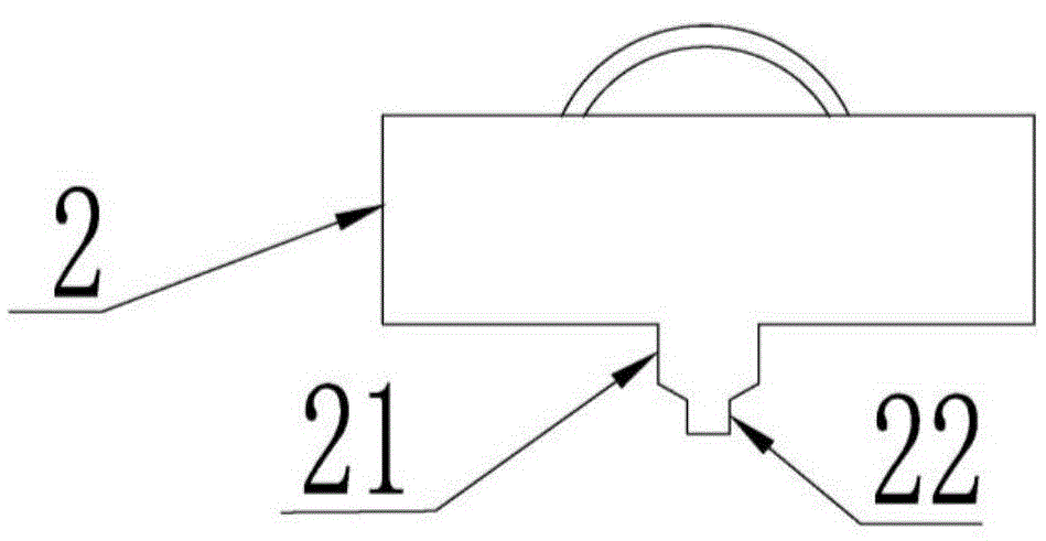
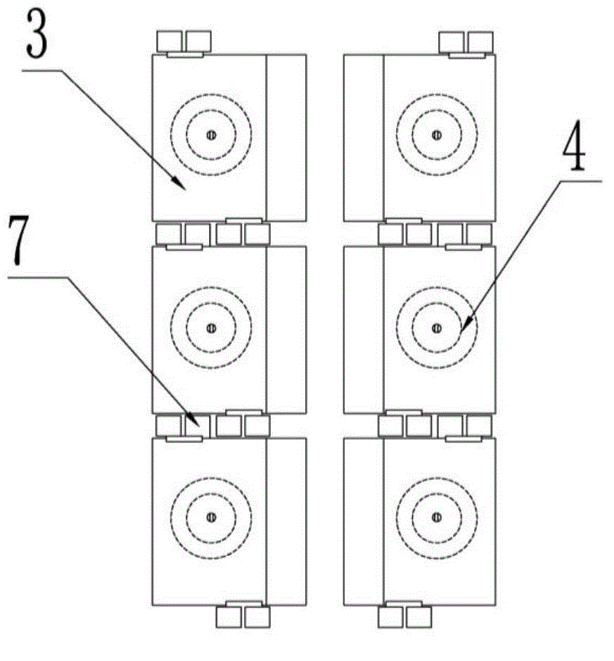
[0054] The self-supporting device for controlling the gap at the root of the suspended weld and welding deformation according to the present invention includes a positioning block 2, an upper rigid pressing block 3, a lower rigid pressing block 5 and a forming groove 6, and a groove is provided in the middle of the forming groove 6 61, the groove 61 is provided with a limit groove 62, the positioning block 2 includes a positioning block body and a positioning part, and the positioning part includes the first-level protrusion 21 on the positioning block body and the first-level The second-stage protruding part 22 on the protruding part 21, the shape of the first-stage protruding part 21 matches the weld root gap 11, and fits in the weld root gap 11, and the limiting groove The shape of 62 is matched with the second-stage protruding portion 22, and the second-stage protruding portion 22 is fitted in the limiting groove 62; the upper rigid pressure block 3 is symmetrically install...

Embodiment 2

[0063] In this embodiment, the device and welding method for self-supporting and controlling the gap at the root of the suspended weld seam and welding deformation are basically the same as in Embodiment 1, but the contact surfaces of the positioning block and the upper and lower rigid pressure blocks are all curved surfaces, so as to be used for welding of curved surface parts , the schematic diagram of the welding process is shown in figure 1 shown. In this embodiment, the thickness of the hull side plate is 4mm, and the butt welding part is a curved surface. Install the square positioning block whose contact surface is a curved surface, the upper and lower rigid pressing blocks, and the forming groove in sequence, and turn on the magnet. The magnets inside the upper and lower rigid pressing blocks will produce an anisotropic magnetic force. Strong pressure restraint, and then start TIG wire filler welding, because there is a forming groove below, the TIG welding single-sid...


PUM

PropertyMeasurementUnit
lengthaaaaaaaaaa
widthaaaaaaaaaa
heightaaaaaaaaaa

Abstract

The invention discloses a device and method for controlling a suspension welding seam root gap and welding deformation in a self-supporting mode. The device comprises a positioning block, upper rigid press blocks, a lower rigid press block and a forming groove. The positioning block comprises a positioning block body and a positioning part, wherein the positioning part penetrates through the seam root gap and is embedded in the forming groove. The upper rigid press blocks are symmetrically installed on the two sides of the positioning block body, the lower rigid press block is provided with provided with an inward-concave part matched with the forming groove, and the forming groove is formed in the inward-concave part. Magnets are installed in the upper rigid press blocks and the lower rigid press block. The invention further discloses the method with the device for controlling the suspension welding seam root gap and the welding deformation in the self-supporting mode used. The device for controlling the suspension welding seam root gap and the welding deformation in the self-supporting mode is convenient to use, low in cost and high in adaptation, the transverse retraction and staggered edges of a welding seam can be controlled, the welding deformation can be reduced, and it can be ensured that the back face of the welding seam is good in formation.

Description

technical field [0001] The invention belongs to the technical field of ship assembly and welding, and in particular relates to a device and method for self-supporting and controlling the gap at the root of a suspended weld seam and welding deformation. Background technique [0002] High-speed ships at home and abroad are mainly welded by aluminum alloys. Because the elastic modulus and yield strength of aluminum alloys are small at temperatures above 200 to 300 degrees Celsius, the deformation resistance is poor; and the thermal conductivity and thermal expansion coefficient of aluminum alloy materials are large. , the welding high-temperature zone is wide, and the welding stress and deformation are relatively large. As a result, when these aluminum hulls are assembled and closed and other suspended positions are welded, the lateral shrinkage of the weld and the welding deformation are much larger than those of the steel section. Orthopedic treatment is required after weldin...

Claims


Application Information

Patent Timeline
Patent Type & Authority Applications(China)
IPC IPC(8): B23K9/00B23K37/04
CPCB23K9/167B23K37/04B23K37/0443B23K2103/10
Inventor 闫德俊罗玖强刘晓莉陈红亮李武凯
Owner CSSC HUANGPU WENCHONG SHIPBUILDING COMPANY
Why Eureka
Try Eureka