Driving shaft of hydraulic pump and machining method thereof

A processing method and driving shaft technology, which are applied to liquid fuel engines, shafts, pump components, etc., can solve the problems of low precision of the hydraulic pump driving shaft, affecting the transmission performance of components, and wear of the hydraulic pump driving shaft, so as to control the scrap rate, Improve the accuracy and ensure the effect of transmission performance

Active Publication Date: 2015-05-20
SUZHOU SABO IND DESIGN
View PDF6 Cites 4 Cited by
  • Summary
  • Abstract
  • Description
  • Claims
  • Application Information

AI Technical Summary

Problems solved by technology

During the movement of the hydraulic pump driving shaft currently used with the plunger cylinder, oil distribution plate or bearing, there is no support surface to support the entire hydraulic pump driving shaft, resulting in serious wear of the hydraulic pump driving shaft; at the same time, when processing the hydraulic pump driving shaft , because there is no machining positioning surface, the precision of the driving shaft of the hydraulic pump produced is low, which in turn affects the transmission performance between various components

Method used


Image

  • Driving shaft of hydraulic pump and machining method thereof
  • Driving shaft of hydraulic pump and machining method thereof

Examples


Embodiment Construction

[0027] In order to make the technical means, creative features, goals and effects achieved by the present invention easy to understand, the present invention will be further described below in conjunction with specific illustrations.

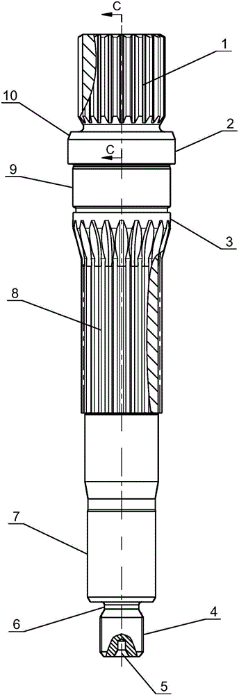
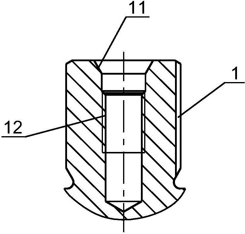
[0028] see Figure 1 ~ Figure 2 The driving shaft of the hydraulic pump includes the first external spline 1, the sealing outer circle 2, the transition outer circle 3, the third outer spline 4, the first thimble cone surface 5, the relief groove 6, the second supporting outer circle 7, The second external spline 8 , the first supporting outer circle 9 , the guide cone surface 10 , the second thimble cone surface 11 and the internal thread 12 .

[0029] In this embodiment, the shaft body of the driving shaft is designed from top to bottom: the first external spline 1 is used to receive external power and drive the driving shaft to rotate; the guide cone surface 10 is used for the installation of the skeleton oil seal; Circle 2 is used for dynam...


PUM

PropertyMeasurementUnit
surface roughnessaaaaaaaaaa

Abstract

A driving shaft of a hydraulic pump comprises a shaft body. A first external spline used for receiving external power to drive the driving shaft to rotate is arranged at the upper end of the shaft body, and a guiding conical surface where a frame oil seal is installed is arranged below the first external spline; a second external spline used for bearing a plunger type cylinder body and driving the plunger type cylinder body to rotate is arranged in the middle of the shaft body, and a first supporting outer circle used for bearing a bearing and playing a role in supporting the entire driving shaft is arranged above the second external spline; a second supporting outer circle and a third external spline are arranged at the lower end of the shaft body, the second supporting outer circle is used for bearing a bearing and playing a role in supporting the entire driving shaft, the third external spline is used for transmitting power to an oil supplementing pump, and the first supporting outer circle and the second supporting outer circle are used for reducing abrasion of the driving shaft of the hydraulic pump; meanwhile, a first ejector pin conical surface and a second ejector pin conical surface which are used for machining positioning of the shaft body are arranged on the two end surfaces of the shaft body. The machining accuracy of the shaft body is improved beneficially, and further transmission performance among assemblies is guaranteed.

Description

technical field [0001] The invention relates to the technical field of variable displacement plunger pumps, in particular to a driving shaft of a hydraulic pump and a processing method thereof. Background technique [0002] The driving shaft of the hydraulic pump is used for power transmission in the variable displacement plunger pump. It receives external power and transmits the power to the charge pump through its own rotation, and cooperates with the plunger to reciprocate with the rotation of the cylinder to complete oil suction and oil pressure. . However, while the driving shaft of the hydraulic pump is performing power transmission, it also needs to bear the load and maintain the structural rigidity because it is often used in conjunction with the plunger cylinder, oil distribution plate or bearings. The currently used hydraulic pump drive shaft has no supporting surface to support the entire hydraulic pump drive shaft during its movement with the plunger cylinder, o...

Claims


Application Information

Patent Timeline
Patent Type & Authority Applications(China)
IPC IPC(8): B23P15/00F04B53/00F16C3/02
CPCB23P15/00F04B53/00F16C3/02
Inventor 张祝周光永沈陆明
Owner SUZHOU SABO IND DESIGN
Why Eureka
Try Eureka