
Automatic warehouse-in and warehouse-out tractor truck for oil tanks

An automatic tractor, warehouse entry and exit technology, applied in the direction of tractors, motor vehicles, traction connectors, etc., can solve the problems of large warehouse renovation projects, affecting warehouse operation efficiency, and small application range, etc., to achieve a wide range of operations and improve Good operational efficiency and mobility

Inactive Publication Date: 2015-05-20
周庆忠
View PDF9 Cites 2 Cited by
  • Summary
  • Abstract
  • Description
  • Claims
  • Application Information

AI Technical Summary

Problems solved by technology

If the warehouse space is modified accordingly, due to the large amount of warehouse renovation work, it will result in a long operation cycle and high cost, which will affect the efficiency of warehouse operation.
If the winch is used for towing, the towing track path cannot be changed with the position of the storage and discharge tanks in the warehouse and the loading and shipping point of the oil tank outside the warehouse due to the fixed installation of the winch, so the maneuverability is poor and the scope of application is small

Method used


Image

  • Automatic warehouse-in and warehouse-out tractor truck for oil tanks
  • Automatic warehouse-in and warehouse-out tractor truck for oil tanks
  • Automatic warehouse-in and warehouse-out tractor truck for oil tanks

Examples


Embodiment Construction

[0035] Embodiments of the present invention will be described in further detail below in conjunction with the accompanying drawings.

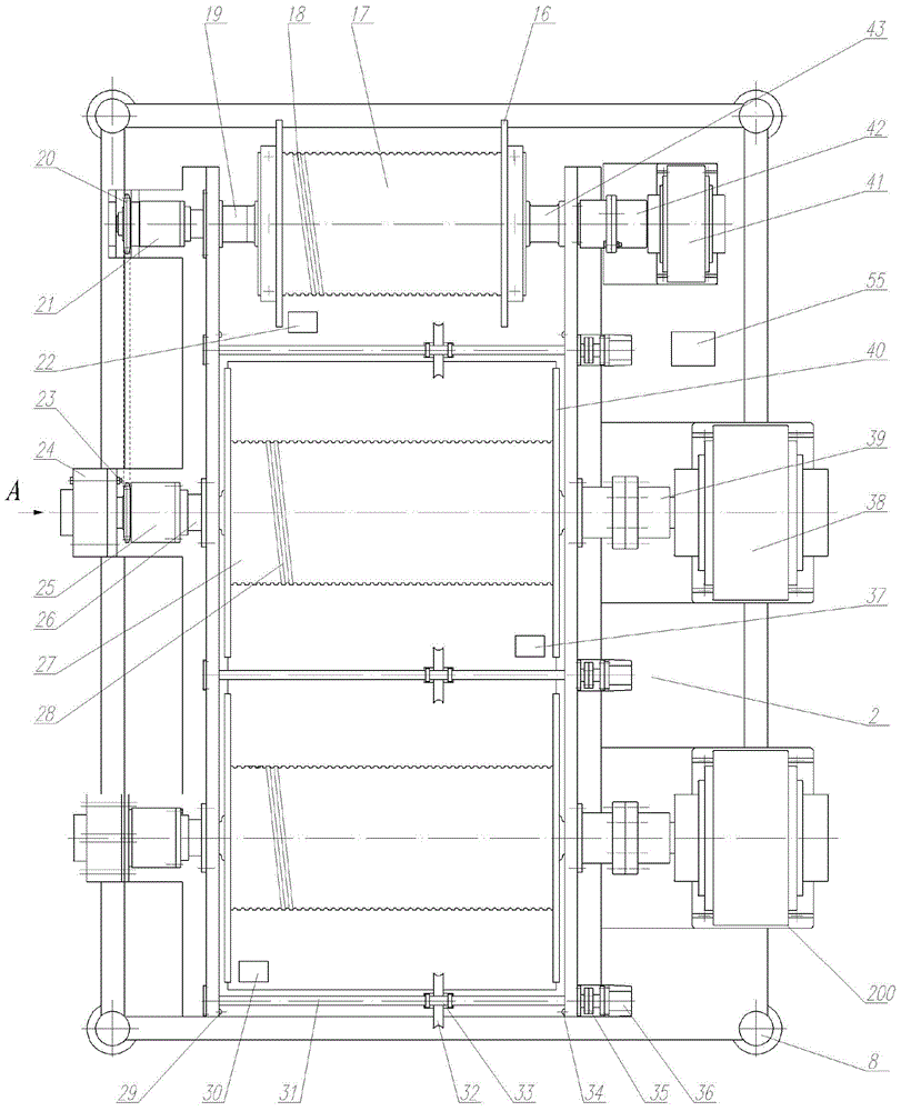
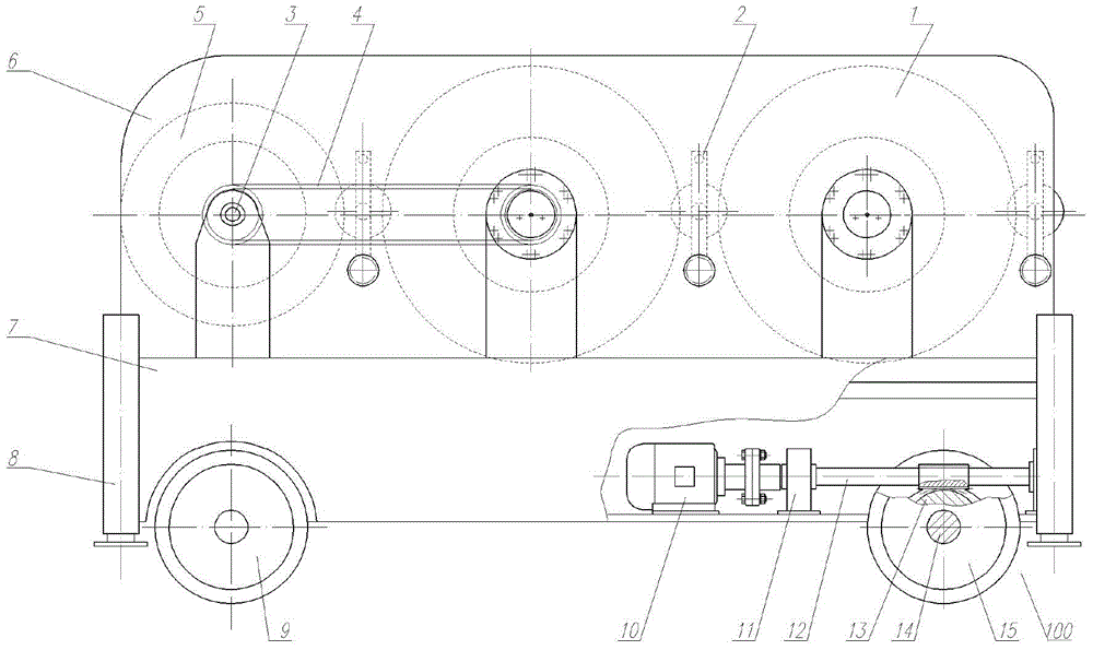
[0036] Such as figure 1 , figure 2 As shown, it is a preferred embodiment of the automatic tractor for the storage of oil tanks, which includes the frame 7 of the tractor, the lower part of the frame 7 is provided with a traveling mechanism 100, and the upper part of the frame 7 is provided with a traction mechanism 200 .

[0037]Described traveling mechanism 100 comprises the front axle that is arranged on vehicle frame 7 front, is arranged on the front wheel 9 of front axle two ends, is arranged on the rear axle 14 of vehicle frame 7 rear, is fixed on the rear wheel 15 of rear axle 14 two ends, A driving device for driving the rear wheel shaft 14 to rotate, and a transmission system arranged between the driving device and the rear wheel shaft 14 to transmit the power of the driving device to the rear wheel shaft 14 .

[0038] Front-wheel ...


PUM


Abstract

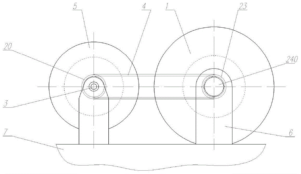
The invention discloses an automatic warehouse-in and warehouse-out tractor truck for oil tanks. The automatic warehouse-in and warehouse-out tractor truck comprises a traveling mechanism, a traction mechanism, rope arrangers and supports. The traveling mechanism is of a four-wheel train structure, and power can be provided for the traveling mechanism by storage batteries. The traction mechanism comprises steel cable drum mechanisms, an electric cable drum mechanism, chain transmission mechanisms, the rope arrangers and the like. Driving force can be provided for the steel cable drum mechanisms by hydraulic motors, and the steel cable drum mechanisms can rotate at identical speeds or differential speeds under the control of the hydraulic motors, so that steel cables can be driven to be wound, and oil tank traction and dragging warehouse-in and warehouse-out operation can be completed. Power of the intermediate hydraulic motor can be transmitted to electric cable drums by means of chain transmission, so that the electric cable drums can synchronously rotate, and electric cables can be wound. Driving force can be provided for the rope arrangers by stepper motors, reciprocating frames can be driven by means of spiral transmission to horizontally move, and accordingly ropes can be arranged in an ordered manner. The supports can be extended and retracted by the aid of hydraulic cylinders, can be extended and supported on the ground during traction operation and can be retracted during traveling. The automatic warehouse-in and warehouse-out tractor truck has the advantages that the automatic warehouse-in and warehouse-out tractor truck is good in movement flexibility, the oil tank warehouse-in and warehouse-out operation intensity can be reduced, and the work efficiency can be improved.

Description

technical field [0001] The invention relates to the field of oil tank transportation, in particular to an automatic tractor for entering and leaving the oil tank. Background technique [0002] Oil tanks are the main oil storage equipment and are widely used in the petroleum industry and national defense logistics support. In order to meet the requirements of national economic construction and national defense construction, it is necessary to reserve a certain number of oil tanks in the oil equipment warehouse. When storing and distributing oil tanks in the warehouse, due to the large size and heavy weight of the oil tanks, they cannot be towed by manpower, and machine towing operations are required, but they are often limited by the space and geographical conditions of the warehouse. If a crane is used for pulling in and out of the oil tank, the warehouse should have a sufficient height to allow the crane to lift and start the operation, and the entrance and exit of the war...

Claims


Application Information

Patent Timeline
Patent Type & Authority Applications(China)
IPC IPC(8): B62D49/00B60D1/01
CPCB60D1/01B62D49/00
Inventor 周庆忠周宇迪熊彪王冰陆思锡王帅李必鑫曾佑军田野曾慧娥
Owner 周庆忠
Learn More