
Electronic control pneumatic type clutch control system and method

A technology of clutch control and control method, applied in the field of clutches, can solve the problems of poor follow-up effect of clutch control, damage to the skin and environment of operators, and increased workload of designers, so as to shorten the response time, achieve universality, The effect of saving maintenance costs

Active Publication Date: 2015-05-20
ZF COMMERCIAL VEHICLE SYSTEMS (QINGDAO) CO LTD
View PDF7 Cites 15 Cited by
  • Summary
  • Abstract
  • Description
  • Claims
  • Application Information

AI Technical Summary

Problems solved by technology

Most of such clutch actuators have the following problems: (1), in the configuration of each vehicle type, it is necessary to carry out the matching design and proofreading of the pedal, the clutch master cylinder and the clutch booster cylinder, which increases the workload of the designer; (2) Since the separation and combination of the clutch is realized by hydraulic control and air assist, the response time of the system during hydraulic transmission becomes the main factor affecting the clutch control. If the hydraulic pipeline is too long, for example, on a passenger car, the clutch pedal If the clutch and booster cylinder are in the rear of the car body, the response time of the system will be prolonged, and the follow-up effect of the clutch control will not be good. The illusion of stepping higher; (3), every car needs to fill and exhaust the system, if the system exhaust is not good, it will lead to incomplete separation of the clutch; (4), the car hydraulic control air assist execution The use of the mechanism will inevitably use brake fluid. During use, if the brake fluid leaks, it will cause certain damage to the operator's skin and the environment; The system needs to be regularly inspected and the brake fluid replenished in time, and the brake fluid should be replaced every two years, which is not only time-consuming and laborious, but also increases maintenance costs

Method used


Image

  • Electronic control pneumatic type clutch control system and method
  • Electronic control pneumatic type clutch control system and method

Examples


Embodiment Construction

[0042] The present invention will be further described in detail below in conjunction with the accompanying drawings and specific embodiments, but the present invention is not limited to these embodiments.

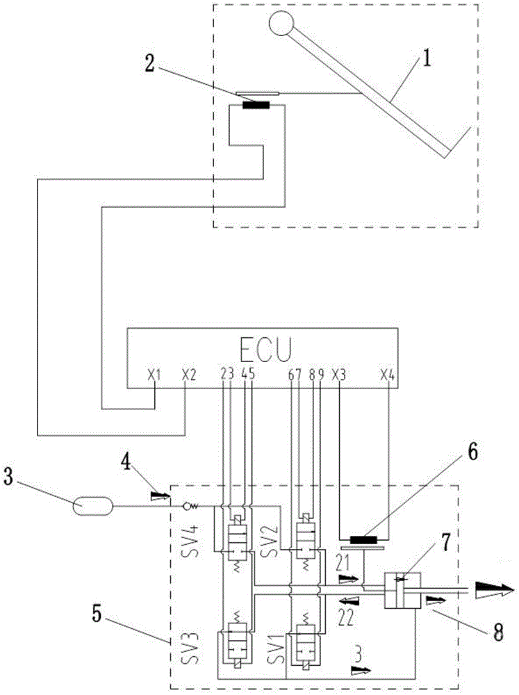
[0043] Such as figure 1 As shown, the electronically controlled pneumatic clutch control system includes an electronic clutch pedal 1, an electronic control unit ECU and a pneumatic clutch actuator. The electronic clutch pedal 1 is provided with a position sensor 2, and the position sensor 2 can be a second displacement sensor or an angle sensor , the position sensor 2 communicates with the electronic control unit ECU to transmit the position information of the pedal to the electronic control unit ECU in time; the pneumatic clutch actuator includes a clutch booster cylinder 5 and an air reservoir 3, and the clutch booster cylinder 5 is provided with an air inlet 4 And the exhaust port 8, the air storage tank 3 is connected with the air inlet 4 of the clutch booster cylinde...


PUM


Abstract

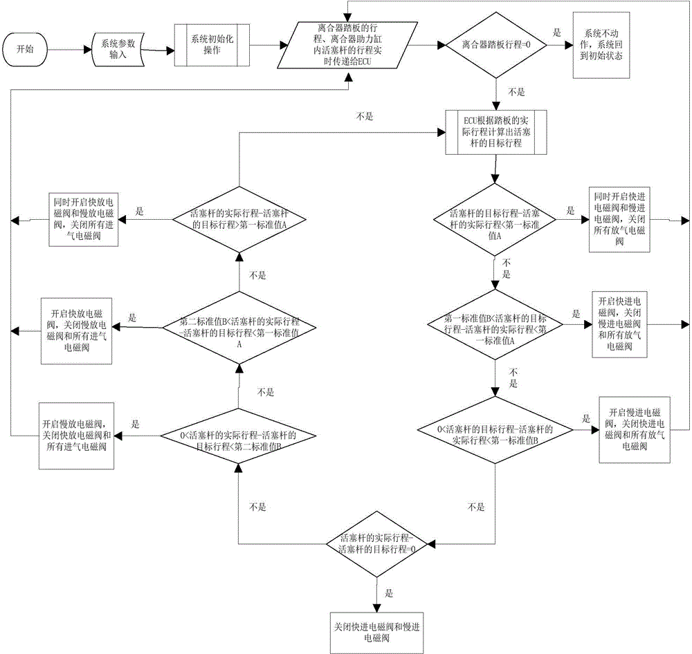
The invention discloses an electronic control pneumatic type clutch control system and method. The control system comprises an electronic clutch pedal, an electronic control unit (ECU) and a pneumatic clutch actuator. The electronic clutch pedal is provided with a position sensor which is in communicating connection with the ECU. The pneumatic clutch actuator comprises a clutch assistance cylinder. A quick release electromagnetic valve, a fast forward electromagnetic valve, a slow release electromagnetic valve and a slow forward electromagnetic valve are arranged in the clutch assistance cylinder. The clutch assistance cylinder is provided with a first displacement sensor. The quick release electromagnetic valve, the fast forward electromagnetic valve, the slow release electromagnetic valve, the slow forward electromagnetic valve and the first displacement sensor are connected with the ECU in a communicating mode. According to the control method, the ECU controls the piston rod stroke in the clutch assistance cylinder by controlling opening and closing of the quick release electromagnetic valve, the fast forward electromagnetic valve, the slow release electromagnetic valve and the slow forward electromagnetic valve. The response time of the system can be effectively shortened, the fast response of clutch control is achieved, and a driver can control a vehicle conveniently.

Description

technical field [0001] The invention relates to a clutch, in particular to an electro-pneumatic clutch control system and control method. Background technique [0002] At present, the most important clutch actuator used in the commercial vehicle market is a hydraulic-controlled air-assisted actuator, which is mainly composed of a clutch pedal, a clutch master cylinder and a clutch booster cylinder. When the driver steps on the clutch pedal, the clutch master cylinder The pressure of the brake fluid is established, and the brake fluid flows along the pipeline to the clutch booster cylinder. When the oil pressure reaches a certain value, the control valve of the clutch booster cylinder opens, and the air pressure enters the clutch booster cylinder. Under the combined action of the push rod, the hydraulic chamber of the clutch booster cylinder accommodates the same amount of brake fluid transferred from the master cylinder, and pushes the clutch release fork, so as to realize t...

Claims


Application Information

Patent Timeline
Patent Type & Authority Applications(China)
IPC IPC(8): F16D48/06
Inventor 蒋培刚
Owner ZF COMMERCIAL VEHICLE SYSTEMS (QINGDAO) CO LTD
Learn More