

Ultra-low nitrogen oxide combustion apparatus using internal recirculation of combustion gas and method therefor
A technology for nitrogen oxides and combustion equipment, which is applied in combustion methods, combustion equipment, and combustion using various fuels, etc., can solve problems such as large space requirements, achieve the effects of stabilizing the flame, simplifying settings, and suppressing overheating.
- Summary
- Abstract
- Description
- Claims
- Application Information
AI Technical Summary
Problems solved by technology
Method used
Image

Examples
Embodiment Construction
[0062] The above objects, features and other advantages of the present invention will become more apparent by describing in detail preferred embodiments of the present invention with reference to the accompanying drawings. The described embodiments are provided illustratively for explaining the invention, and do not limit the technical scope of the invention.
[0063] The constituent elements constituting the ultra-low nitrogen oxide combustion equipment of the present invention can be used as a whole or separately. Furthermore, depending on the form of use, some of the constituent elements may be omitted.
[0064] Hereinafter, an ultra-low nitrogen oxide combustion device according to an embodiment of the present invention will be described in detail with reference to the accompanying drawings.
[0065] Explanation of the overall structure of ultra-low nitrogen oxide combustion equipment
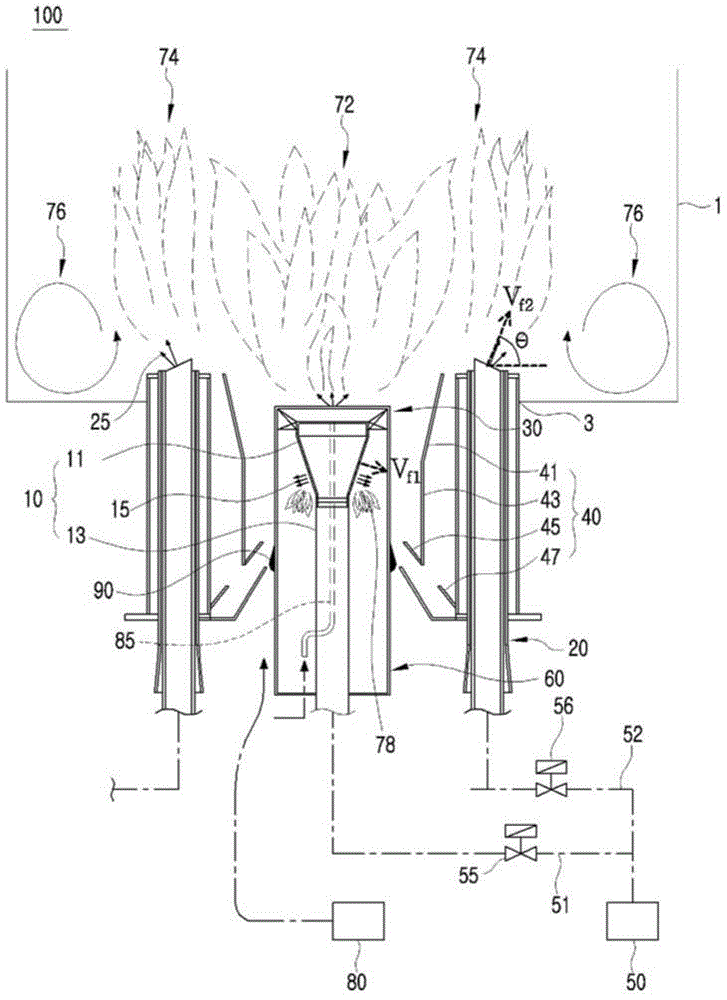
[0066] First, refer to figure 1 , the overall structure of the ultra-low nitrogen ...
PUM
 Abstract
Description
Claims
Application Information