High-frequency rotary precision-forging compounding method for metal composite tube and rod manufacturing

A technology of metal composite pipes and metal pipes, which is applied in the direction of manufacturing tools, metal processing equipment, hammer driving devices, etc., can solve the problems of poor bonding strength of composite steel pipes, fast wear of hammer heads, low efficiency, etc., and achieve smooth product appearance The effect of high precision, low site requirements and short process flow

Active Publication Date: 2015-05-27
李富申 +1
View PDF7 Cites 11 Cited by
  • Summary
  • Abstract
  • Description
  • Claims
  • Application Information

AI Technical Summary

Problems solved by technology

The disadvantage of the composite steel pipe produced by this method is that in many cases, the surface of the tube billet must be machined, which increases the uneven wall thickness of the two layers of metal, and the transition will be formed due to the mutual washing and mixing of liquid metal during casting. Floor
In addition, this method cannot produce composite pipes whose outer layer is light alloy
[0004] The second is thermal processing, such as extrusion or rolling; the disadvantages of this method are large power consumption, large equipment, and poor bonding strength of composite steel pipes produced by it.
[0005] The third is the cold drawing method, and its disadvantages are poor bonding strength, uneven tube density, and low yield
[0006] The fourth is the cladding welding method, the disadvantage of which is that it is difficult to produce inner composite steel pipes with thin-walled inner layers
[0007] The fifth is the explosive composite method. Its disadvantage is that the interface joint area is easy to form a waveform, and the temperature of the tube blank is limited. It is necessary to build a special explosion site or sp

Method used


Image

  • High-frequency rotary precision-forging compounding method for metal composite tube and rod manufacturing
  • High-frequency rotary precision-forging compounding method for metal composite tube and rod manufacturing

Examples


Embodiment Construction

[0025] The present invention and its beneficial technical effects will be further described in detail below in conjunction with the accompanying drawings and preferred embodiments.

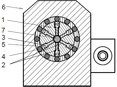
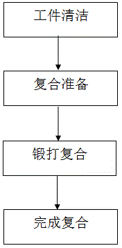
[0026] see figure 1 , a high-frequency rotary precision forging composite method for the manufacture of metal composite tubes and rods, which mainly includes the following process steps: (1) Clean the workpiece, and clean the surface of the metal tube / metal rod to be composited by physical or chemical processes; (2) ) Composite preparation, put the outer metal tube on the metal tube / metal rod as the inner liner / liner rod, and fix and position the two ends of the outer metal tube with the metal tube / metal rod to form a compound to be compounded Metal composite pipe / rod; if the inner liner is a metal pipe, a core rod needs to be inserted into the metal pipe; (3) Forging and compounding, the metal composite pipe / rod to be composited is placed in a high-frequency rotary precision forging machine The ...


PUM


Abstract

The invention discloses a high-frequency rotary precision-forging compounding method for metal composite tube and rod manufacturing. The high-frequency rotary precision-forging compounding method comprises the following main process steps: (1) cleaning workpieces; (2) preparing for compounding; (3) forging and compounding: putting to-be-compounded metal composite tubes/rods on a feeding rack of a high-frequency rotary precision-forging machine, introducing the to-be-compounded metal composite tubes/rods into the high-frequency rotary precision-forging machine to forge under the pushing of a feeding system of the high-frequency rotary precision-forging machine, and forging until inner and outer layers of composite metal tubes/rods are tightly compounded; (4) completing the compounding: if lining tubes at the inner layer are metal tubes, dropping out core rods. The high-frequency rotary precision-forging compounding method has the advantages of low power consumption, easy operation, high product manufacturing efficiency, high bonding strength, high product surface flatness, short process flow and safe production. Compared with an existing process, the cost of the equipment is greatly reduced, the maintenance cost is relatively low and the requirements on field are relatively low; a plurality of layers of different metal tube rods can also be compounded in a multi-layer mode.

Description

technical field [0001] The invention relates to a manufacturing process of a metal composite pipe or a metal composite rod, in particular to a method for compounding pipes and rods of different metal materials through a rotary forging technology. Background technique [0002] The manufacturing process of metal composite pipe and rod is currently widely used in the following categories: [0003] The first is the centrifugal casting method; this is a force method that obtains bonding based on the interaction of molten metal with solid metal. The disadvantage of the composite steel pipe produced by this method is that in many cases, the surface of the tube billet must be machined, which increases the uneven wall thickness of the two layers of metal, and the transition will be formed due to the mutual washing and mixing of liquid metal during casting. layer. In addition, this method cannot produce a composite pipe whose outer layer is a light alloy. [0004] The second is the...

Claims


Application Information

Patent Timeline
IPC IPC(8): B21J5/06B21J7/16B21J1/00B21J7/30
Inventor 李富申黎建
Owner 李富申
Why Eureka
Try Eureka