

Water circulating device for waste rubber pyrolysis production line
A production line and circulating water technology, applied in the petroleum industry, the preparation of liquid hydrocarbon mixtures, and the treatment of hydrocarbon oil, etc., can solve the problem that cooling water cannot meet production needs, reduce production costs, increase oil yield, and increase cooling speed Effect
- Summary
- Abstract
- Description
- Claims
- Application Information
AI Technical Summary
Problems solved by technology
Method used
Image

Examples
Embodiment Construction
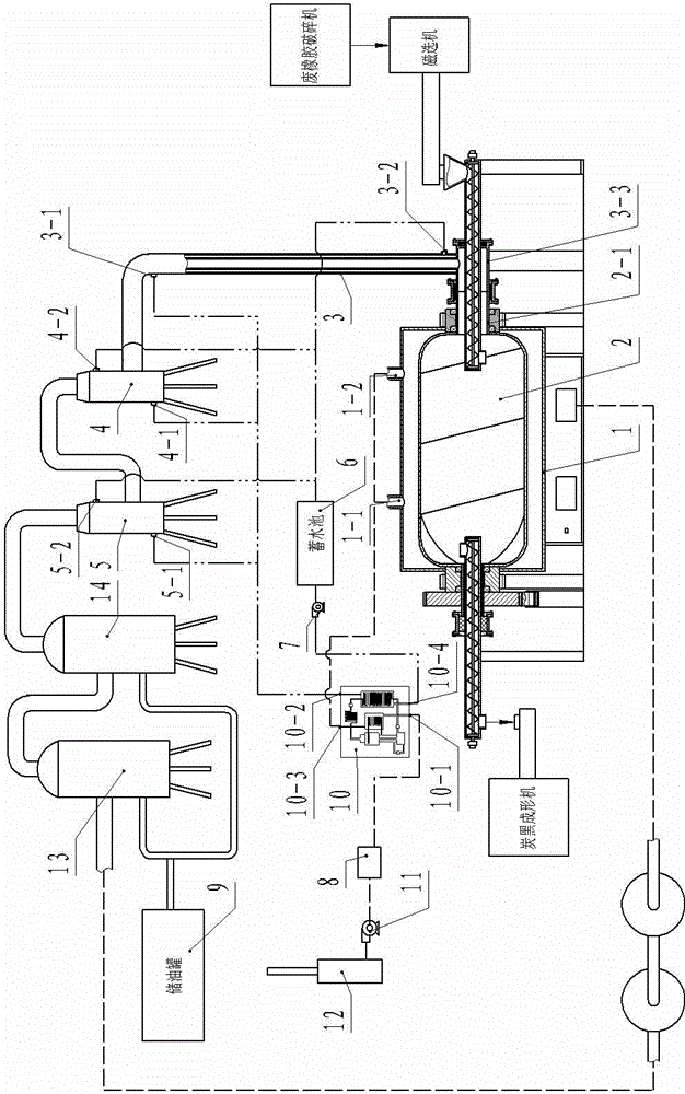
[0012] Below in conjunction with accompanying drawing example the present invention is described in further detail:
[0013] Such as figure 1 The shown circulating water device of the waste rubber cracking production line includes a cracking kettle. The cracking kettle has a kettle body 2 and a kettle cover 1 installed outside the kettle body 2. The hollow shaft 2-1 at one end of the body 2 communicates with the water-cooled air pipe 3 provided with an outer water jacket through the connecting pipe 3-3, and the water-cooled air pipe 3 communicates with the air inlet of the primary cooler 4. The air outlet of cooler 4 is connected with the air inlet of secondary cooler 5 through pipeline; The gas outlet of 14 is communicated with the air inlet of secondary oil-gas separator 13 through pipeline; The outer water jacket of the water-cooled air pipe 3 has a water inlet 3-1 and a water outlet 3-2, the primary cooler 4 has a water inlet 4-1 and a water outlet 4-2, and the secondary...
PUM
 Abstract
Description
Claims
Application Information