Self-holding electromagnetic valve

A solenoid valve, self-maintaining technology, applied in the direction of lift valve, valve details, valve device, etc., can solve the problems of complex processing technology, uneven magnetic force, unstable quality, etc., and achieve the effect of reducing manufacturing cost and saving electric energy.

Active Publication Date: 2015-05-27
XINGYU ELECTRON NINGBO CO LTD
View PDF10 Cites 7 Cited by
  • Summary
  • Abstract
  • Description
  • Claims
  • Application Information

AI Technical Summary

Problems solved by technology

[0004] Another patent number is 201220167984.9, a Chinese patent titled "a self-holding solenoid valve" discloses a self-holding solenoid valve, which uses only one permanent magnet in the coil to realize the self-holding function of the solenoid valve; however, ordinary The permanent magnet will lose part of the magnetic force due to high temperature during the coil injection molding process, resulting in uneven magnetic force and unstable quality, and the cost of using high-temperature permanent magnets will also greatly increase the manufacturing cost
[0005] There are also some solenoid valves that use a double-coil structure to achieve self-holding functions, such as 200920126847.9 and 201120383164.9; the use of a double-coil structure will not only increase the manufacturing cost, but also complicate the processing process

Method used


Image

  • Self-holding electromagnetic valve
  • Self-holding electromagnetic valve
  • Self-holding electromagnetic valve

Examples


Embodiment Construction

[0026] The present invention will be further described in detail below in conjunction with the accompanying drawings and embodiments.

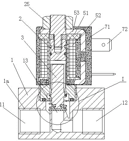
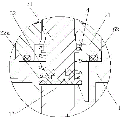
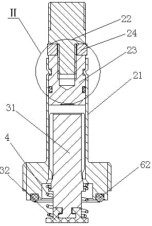
[0027] Such as Figure 1 to Figure 5 Shown is the structural representation of the present invention,

[0028] The reference signs are: valve body 1, connecting thread 1a, inlet 11, outlet 12, valve port 13, fixed iron core assembly 2, casing 21, first fixed iron core 22, second fixed iron core 23, annular Groove 23a, sealing ring groove 23b, permanent magnet 24, nut 25, movable iron core assembly 3, movable iron core 31, gasket 32, annular edge 32a, spring 4, bobbin 51, winding 52, coil magnetic frame 53. The first sealing ring 61, the second sealing ring 62, the housing 71, and the electrical plug-in 72; the direction of the arrow in the figure indicates the flow direction of the medium.

[0029] Such as Figure 1 to Figure 5 as shown,

[0030] A self-holding solenoid valve, comprising a valve body 1, an inlet 11 and an outlet 12 are arr...


PUM


Abstract

The invention discloses a self-holding electromagnetic valve, which comprises a valve body, wherein an inlet and an outlet are formed in the valve body, a fixed iron core assembly is assembled at the upper part of the valve body, the fixed iron core assembly consists of a sleeve, a first fixed iron core, a second fixed iron core and a permanent magnet, the center of the sleeve is vertically provided with an open hole, the first fixed iron core is made of non-magnetic-conduction stainless steel materials, the second fixed iron core is made of soft magnetic materials, the permanent magnet is arranged between the first fixed iron core and the second fixed iron core, the second fixed iron core is fixedly arranged at the upper end of the sleeve, the first fixed iron core is fixedly arranged on the second fixed iron core, a movable iron core assembly is arranged in the sleeve of the fixed iron core assembly, the lower end of the movable iron core assembly is matched with a valve opening formed in the valve body, a spring is arranged outside the lower part of the movable iron core assembly in a sleeving way, the upper end of the spring is abutted against the fixed iron core assembly, the lower end of the spring is abutted against the movable iron core assembly, a reel is arranged outside the fixed iron core assembly, and a winding and a coil magnetic conduction frame are arranged on the reel. The self-holding electromagnetic valve has the advantages that the structure is simple, the manufacturing cost is low, and the self-holding state is stable.

Description

technical field [0001] The invention relates to the technical field of electromagnetic valve manufacturing, in particular to a self-holding electromagnetic valve. Background technique [0002] A general solenoid valve consists of an excitation coil, a fixed iron core, a compression spring, a movable iron core, and a valve body. Its working principle is that when the excitation coil is not energized, the sealing head of the fixed iron core will close the valve under the action of the compression spring and the back pressure of the valve inlet medium. When the excitation coil is energized, the electromagnetic force overcomes the reaction force of the compression spring and the back pressure of the inlet medium of the valve, so that the movable iron core moves to the fixed iron core until the two planes are attracted, and the valve is in the open state. It can keep the valve in the open state only when it is powered on, so it has the disadvantages of large power consumption an...

Claims


Application Information

Patent Timeline
Patent Type & Authority Applications(China)
IPC IPC(8): F16K31/06F16K1/00
CPCF16K1/32F16K31/0655F16K31/0675
Inventor 曹建波章苗英
Owner XINGYU ELECTRON NINGBO CO LTD
Why Eureka
Try Eureka