Multistage matching energy supply device and process

A technology for energy supply and equipment, applied in mechanical equipment, gas/liquid distribution and storage, pipeline systems, etc., can solve problems such as inability to meet production requirements, unstable system operation, equipment damage, etc., to achieve a wide range of applications and maintain stability performance, and the effect of reducing the number of units

Active Publication Date: 2015-05-27
CHINA TIANCHEN ENG +2
View PDF6 Cites 2 Cited by
  • Summary
  • Abstract
  • Description
  • Claims
  • Application Information

AI Technical Summary

Problems solved by technology

[0007] As mentioned in the above two examples, the same energy supply equipment cannot meet the production requirements
Frequent adjustment of the output medium level of the energy supply equipment is likely to cause damage to the equipment and make the system unstable

Method used


Image

  • Multistage matching energy supply device and process

Examples


Embodiment 1

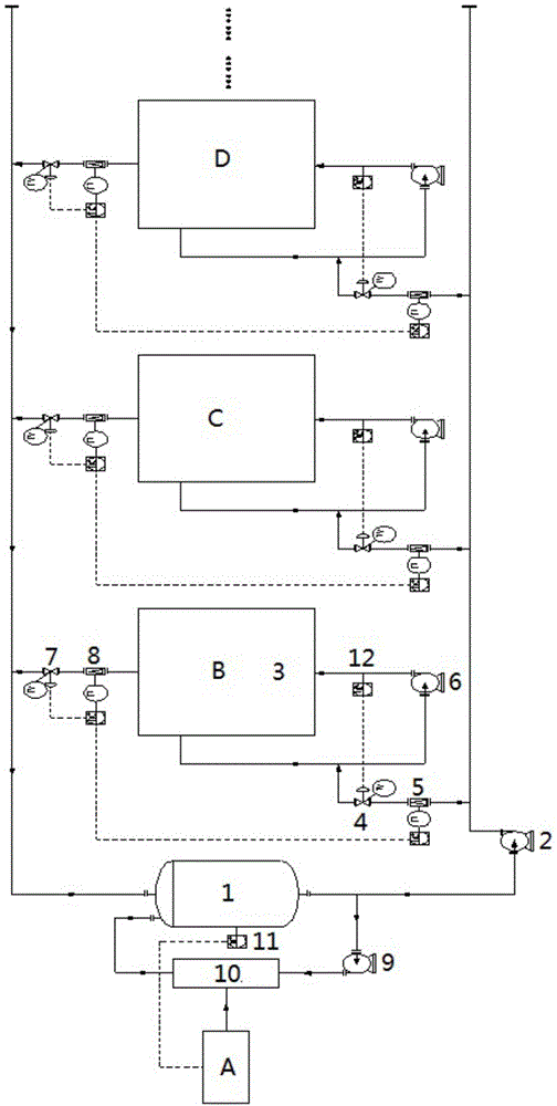
[0036] The energy supply medium is heat conduction oil. After the heat conduction oil is filled in the system, firstly turn on the forced circulation pump 9 of the energy supply equipment, use the energy exchange equipment 10 to heat the heat conduction oil, and then return to the energy supply medium storage tank 1, through the energy supply The medium temperature transmitter 11 controls, and after the heat transfer oil reaches the temperature set by the system of 250°C, the energy supply medium pump 2 is turned on to deliver the heat transfer oil to each user.

[0037] Assuming that user one B is a heat exchanger, the temperature of the heat exchange medium is required to be controlled at 150°C. The heat transfer oil enters the tube side of the heat exchanger. Through the user's forced circulation pump 6, the heat transfer oil is fully mixed and the temperature is uniform. Through the user's temperature transmitter 12, set the target temperature as 150°C. The temperature c...

Embodiment 2

[0041] The energy supply medium is hot water. After the hot water is filled in the system, the hot water forced circulation pump 9 is first turned on, and the waste heat recovery heat exchanger 10 of the system is used to raise the temperature of the hot water, and then returns to the hot water tank 1. Controlled by the water temperature transmitter 11, when the hot water reaches the system-set temperature of 90° C., the hot water pump 2 is turned on to deliver the hot water to each user.

[0042] Assuming that user one B is a fermentation tank, the temperature of the material in the tank is required to be controlled at 45°C. The hot water enters the hot water jacket of the fermentation tank, and the fermentation is carried out at a constant temperature. The forced circulation pump 6 through the heat exchanger makes the hot water fully mixed and the temperature uniform. Through the heat exchanger temperature transmitter 12, considering a certain temperature difference between...

Embodiment 3

[0046] The energy supply medium is ethylene glycol. After the ethylene glycol is filled in the system, the ethylene glycol forced circulation pump 9 is first turned on, and the Freon compressor 10 is used to cool the ethylene glycol for heat exchange, and then return to the ethylene glycol tank 1 , controlled by the ethylene glycol temperature transmitter 11, after the ethylene glycol reaches the temperature set by the system -15°C, the ethylene glycol pump 2 is turned on, and the ethylene glycol is delivered to each cooling user.

[0047] Let User 1B be a heat exchanger, which cools the water to 10°C, and the heat exchange temperature is required to be controlled above 0°C. Ethylene glycol enters the tube side of the heat exchanger. Through the forced circulation pump 6 of the heat exchanger, the ethylene glycol is fully mixed and the temperature is uniform. Through the heat exchanger temperature transmitter 12, set the target temperature as 1°C. The temperature control val...


PUM


Abstract

The invention discloses a multistage matching energy supply device. The multistage matching energy supply device comprises an energy supply device and energy utilizing users, wherein a parallel structure is arranged between the energy supply device and the energy utilizing users; the number of the energy utilizing users is larger than or equal to 1; the multistage matching energy supply device also comprises an energy supply medium pump, a temperature control valve, an energy supply medium inlet flow transmitter, a user forced circulation pump, a flow adjusting valve, an energy supply medium outlet flow transmitter and a user temperature transmitter; the energy supply medium pump is mounted on an energy supply main pipe; the user forced circulation pump, the user temperature transmitter and the energy utilizing users are in pipeline connection with one another to form an inner circulation structure of a medium; the energy supply pipeline is connected to the inner circulation structure; the temperature control valve and the energy supply medium inlet flow transmitter are mounted on the energy supply pipeline; a flow returning pipeline is connected to the energy utilizing users and a flow returning main pipe; the flow adjusting valve and the energy supply medium outlet flow transmitter are mounted on the flow returning pipeline.

Description

technical field [0001] The invention belongs to the technical field of chemical technology, and in particular relates to a multi-stage matching energy supply equipment and technology. Background technique [0002] The chemical industry is a high-energy-consuming industry. The core theory in the chemical industry is "three transmissions and one reversal", namely energy transfer, mass transfer, momentum transfer and reaction engineering. Energy transfer is very common in chemical plants, and the processes of heating, cooling, evaporating, condensing, and heat tracing of materials and public engineering media are all concrete manifestations of energy transfer. Efficient use of energy, reasonable distribution of energy, making chemical equipment more environmentally friendly, reducing unit consumption of products, thereby reducing costs and increasing profits are the constant pursuit of chemical researchers and designers. [0003] Many different types and specifications of util...

Claims


Application Information

Patent Timeline
Patent Type & Authority Applications(China)
IPC IPC(8): F17D1/14
Inventor 陈宁魏建民李强王兵杨光裴艳红魏浩然靳权张冰汪浩张洪江
Owner CHINA TIANCHEN ENG
Why Eureka
Try Eureka