Cement kiln waste-heat utilization system and method for directly driving rotating equipment by turbine

A technology for rotating equipment and steam turbines, applied in mechanical equipment, cement production, steam engine installations, etc., can solve the problems of large energy loss, achieve the effect of avoiding energy loss and improving the efficiency of waste heat recovery and utilization

Active Publication Date: 2015-05-27
NANJING KESEN KENEN ENVIRONMENT & ENERGY
View PDF5 Cites 5 Cited by
  • Summary
  • Abstract
  • Description
  • Claims
  • Application Information

AI Technical Summary

Problems solved by technology

[0004] Aiming at the large energy loss of the existing cement kiln waste heat power generation system, the present invention aims to provide a cement kiln waste heat utilization system and method in which the steam turbine directly drives the rotating equipment, so as to achieve the purpose of improving the recovery and utilization rate of cement kiln waste heat

Method used


Image

  • Cement kiln waste-heat utilization system and method for directly driving rotating equipment by turbine
  • Cement kiln waste-heat utilization system and method for directly driving rotating equipment by turbine

Examples


Embodiment Construction

[0024] The present invention will be further described below in conjunction with the drawings and embodiments.

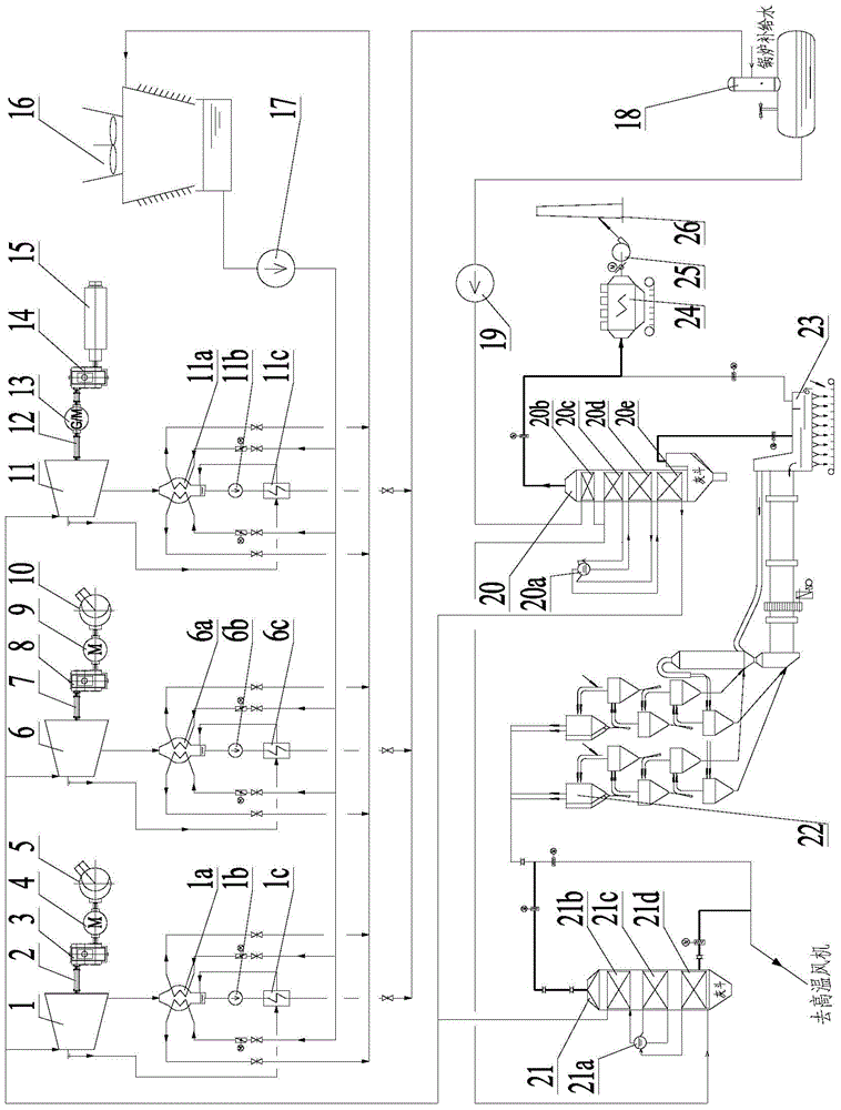
[0025] Such as figure 1 As shown, a cement kiln waste heat utilization system with a steam turbine directly driving rotating equipment includes a waste heat recovery device, a high-temperature fan turbine drive device, a kiln exhaust fan turbine drive device, a cement mill steam wheel drive device, and a circulating cooling water device And exhaust gas treatment device.

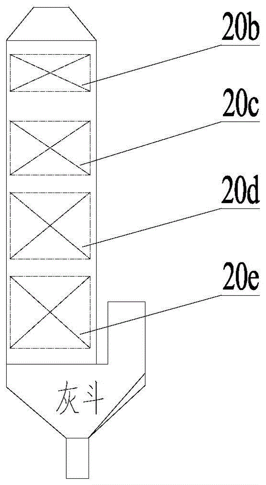
[0026] The waste heat recovery device mainly includes a deaerator 18, a feed water pump 19, a kiln head boiler 20, a kiln tail boiler 21, a kiln tail preheater 22 and a grate cooler 23; the outlet of the deaerator 18 is connected to the inlet of the feed water pump 19, The outlet of the feed water pump 19 is connected to the inlet of the public economizer 20b of the kiln-head boiler 20. The air inlet in the middle of the grate cooler 23 is connected to the inlet of the kiln-head boiler 20 through a duct...


PUM


Abstract

The invention provides a cement kiln waste-heat utilization system and a method for directly driving rotating equipment by a turbine. The system and the method belong to the technical field of cement kiln waste-heat utilization. The waste-heat utilization system comprises a waste-heat recovery device, a high-temperature fan turbine drive device, a kiln tail exhaust fan turbine drive device, a cement grinding mill turbine drive device and a circulating cooling water device. According to the system and the method, superheated steam generated by the cement kiln waste heat is utilized to directly drive rotating equipment such as a high-temperature fan, a kiln tail exhaust fan and a cement grinding mill, the energy loss during the multistep energy transformation process from heat energy to electric energy to kinetic energy of waste heat power generation is avoided, and the cement kiln waste heat recovery and utilization efficiency is effectively improved.

Description

Technical field [0001] The invention belongs to the technical field of cement kiln waste heat recovery and utilization, and specifically relates to a cement kiln waste heat utilization system and method in which a steam turbine directly drives a rotating device. Background technique [0002] The waste heat discharged by cement kilns during the production process mainly consists of two parts: ① the hot air discharged from the kiln head grate cooler; ② the exhaust gas discharged from the C1 cylinder of the kiln tail preheater. At present, for the above two parts of waste heat, the kiln head waste heat boiler and the kiln tail waste heat boiler are mainly used to recover and generate superheated steam, and then the superheated steam from the two waste heat boilers is combined and sent to the turbine generator set through the steam main pipe. Power generation, the generated energy can be used for the production of cement plants. [0003] The energy conversion process in this cement ki...

Claims


Application Information

Patent Timeline
IPC IPC(8): F27D17/00F01K11/02F01D15/10
CPCY02P10/25Y02P40/121Y02P80/15
Inventor 侯宾才方明王朝雄刘亚雷刘木堂
Owner NANJING KESEN KENEN ENVIRONMENT & ENERGY
Why Eureka
Try Eureka