A method for controlling needle marks in wafer high temperature testing

A wafer, high-temperature technology, applied in the direction of electronic circuit testing, components of electrical measuring instruments, measuring electricity, etc., can solve the problems of affecting the effect of needle marks and unsatisfactory effects

Active Publication Date: 2018-02-13
浙江确安科技有限公司
View PDF5 Cites 0 Cited by
  • Summary
  • Abstract
  • Description
  • Claims
  • Application Information

AI Technical Summary

Problems solved by technology

For example, according to the routine process of high-temperature testing, it can be concluded that the thickness, radius, and length of the probe will change for each batch of testing. The conventional process of high-temperature testing only performs warming on the first wafer of each batch. However, when the test is completed after the current wafer is replaced, there will be a period of interval time. During this interval time, the probe is in a non-contact shelving state. At this time, the probe will change with the ambient temperature. As the temperature keeps changing, the length of the needle mark will also change, which will affect the effect of the needle mark
Although there is also a method for correcting needle marks, the effect is not ideal

Method used


Image

  • A method for controlling needle marks in wafer high temperature testing
  • A method for controlling needle marks in wafer high temperature testing
  • A method for controlling needle marks in wafer high temperature testing

Examples


Embodiment Construction

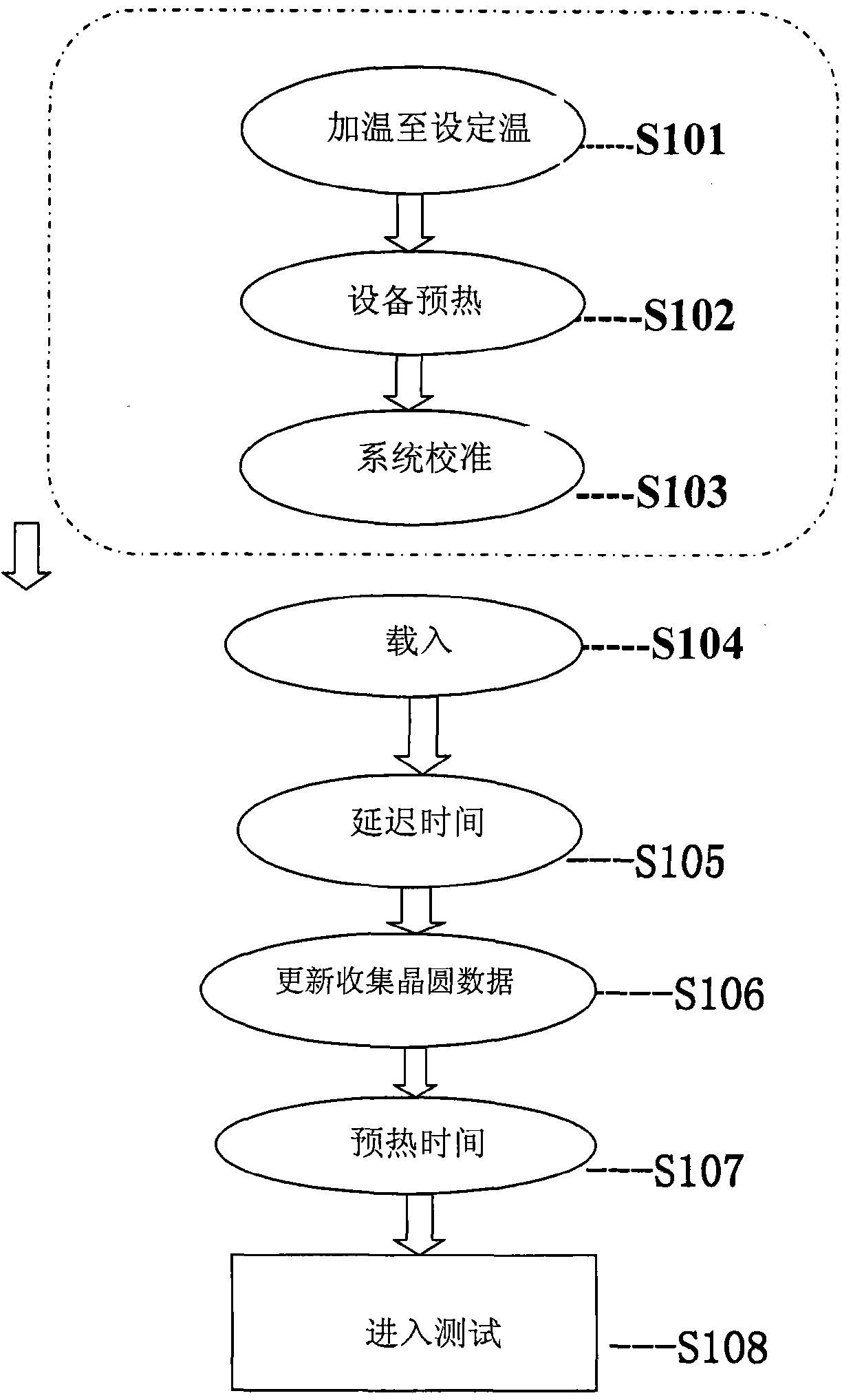
[0014] refer to figure 1 The steps shown, S101-S103 are the preparatory work before the high-temperature test, as long as the high-temperature test state is not changed after being set once, there is no need to redo the process again. First, step S101 is heating to a set temperature. That is to say, the equipment is heated up to the set temperature of high temperature, there may be a difference of two degrees, and the heating time is 6 minutes. During the heating process, the position of the slide table should be moved to the initial position. Next, step S102 is to preheat the equipment. After heating up to the set temperature, the equipment is left to stand for 120 minutes, the purpose of which is to establish a high-temperature environment inside the equipment, so that the alignment calibration step can reach a stable state under the high-temperature environment. Then, step S103 is a system calibration step, that is, after preheating, the accuracy of each part of the probe...


PUM


Abstract

The present invention provides a method for controlling needle marks in wafer high-temperature testing. The following steps are performed in sequence: a loading step, loading the wafer to be tested into a loading table, and a delaying step, before testing the wafer to be tested, Delay for a certain time, update and collect data step, update and collect the data of the wafer to be tested, test step, test the wafer to be tested. The effect of the present invention is to avoid the precision change after the deformation of each part of the probe station caused by the temperature change, thereby causing the needle mark effect and the resulting quality accidents such as abnormal wafer test results and wafer loss.

Description

technical field [0001] The invention belongs to the technical field of integrated circuit testing, and in particular relates to a method for controlling needle marks when performing high-temperature testing on wafers. Background technique [0002] In the routine testing of wafers, the equipment is routinely set up according to the standard steps established in the operation manual to realize the automatic testing connected with the testing machine. When performing high-temperature tests, the temperature changes will cause physical changes to various precise components of the device itself, including the probe card. This will cause errors in the alignment of the probe and the pressure point when testing the product. The alignment process is to measure whether the position of the probe is consistent with the position of the pressure point on the wafer die through the equipment microscope, so as to ensure that the needle mark will not deviate from the pressure point. point ran...

Claims


Application Information

Patent Timeline
Patent Type & Authority Patents(China)
IPC IPC(8): G01R1/067G01R31/28
Inventor 李亮杨振宇石志刚韩顺宝杨颖超
Owner 浙江确安科技有限公司
Why Eureka
Try Eureka