Diopter-adjustable curved surface waveguide near-to-eye optical display device

A curved surface and waveguide technology, which is applied in the field of curved surface waveguide near-eye optical display devices, can solve the problems such as the inability to reduce the thickness of the device, the difficulty, and the difficulty of increasing the design, so as to achieve simple and easy optical design and processing technology, and improve the contrast of the image , The effect of simple and easy manufacturing process

Active Publication Date: 2015-05-27
SHANGHAI RAYPAI PHOTONIC CRYSTAL LTD
View PDF11 Cites 57 Cited by
  • Summary
  • Abstract
  • Description
  • Claims
  • Application Information

AI Technical Summary

Problems solved by technology

[0004] In order to solve a series of problems caused by the weight, field of view and external diopter adjustment of the traditional wearable display optical system, the US Patent US7736006B2 applied by Micro Vision Company of the United States provides a display technology solution, which uses a polarizing substrate to achieve The transformation of the polarization state of the light wave allows the large-angle S light to reflect and image, and the small-angle P light to completely pass through the reflective surface. The projected area of ​​the bottom surface is too small, which is not conducive to the expansion of the field of view, and at the same time increases the difficulty of design, which leads to the inability to reduce the thickness of the device
U.S. Patent US20100260455 uses a micro-sawtooth structure to expand the display field of view of the display device, but the overall thickness of the device is not reduced, and the overall appearance of the device is not good enough to bring comfort to the wearer.
In U.S. Patent No. 7,021,777, the expansion of the field of view of the display device and the thinning of the display device are achieved by using a light-conducting flat panel, but the technical solution is very difficult to implement in terms of the specific design and process of the device. The extended range of display field of view is limited, these factors make the device unsuitable for mass production
More importantly, although the planar waveguide near-eye optical display system mentioned in the above patent has improved in terms of weight, volume and field of view expansion, there is no substantial change in the internal adjustment of diopter

Method used


Image

  • Diopter-adjustable curved surface waveguide near-to-eye optical display device
  • Diopter-adjustable curved surface waveguide near-to-eye optical display device
  • Diopter-adjustable curved surface waveguide near-to-eye optical display device

Examples


Embodiment Construction

[0024] The specific implementation process of the present invention will be described below in conjunction with the accompanying drawings.

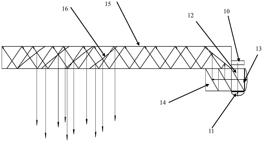
[0025] figure 1 It is a structural schematic diagram of the adjustable diopter curved waveguide near-eye optical display device of the present invention. Such as figure 1As shown, the system composition of the present invention includes an image display light source 10, a collimating lens group 11, a PBS polarization splitting component 12, a P&S light conversion component 13, a P&S splitting selection component 14, a micro-curved waveguide substrate 15 and a micro-local curvature coupling output Face 16. The image shows that the light from the light source 10 enters the PBS polarization beam splitting assembly 12, first the S light from the light source passes through the reflection of the polarization beam splitting assembly 12 and the conversion of the P&S light conversion assembly 13, so that the S light becomes P light and enters t...


PUM


Abstract

The invention provides a diopter-adjustable curved surface waveguide near-to-eye optical display device which comprises an image display light source used for providing image information used for observation, a collimating lens set used for collimating optical waves, a PBS (polarization beam-splitting) assembly used for performing polarization beam-splitting on the optical waves, a P&S photo-conversion assembly used for realizing conversion of P light and S light, a P&S beam-splitting selection assembly capable of enabling the optical waves to uniformly cover a coupling input surface, a micro-curved surface waveguide substrate used for performing total-reflection propagation on the optical waves, and a micro-local curvature coupling output surface used for enabling the transmitted optical waves to be coupled and output out of the substrate, expanding a view field angle and adjusting the diopter. The diopter-adjustable curved surface waveguide near-to-eye optical display device has the advantages of adjustable diopter, lightweight, thinness, large view field angle, simplicity for processing and design, easiness for realization, compact structure and high energy utilization rate of an image source, can be used in various fields of remote medical information teaching, virtual reality simulation training, fire rescue information positioning guidance, road enhancement display and the like, and can be used as a display of a terminal.

Description

technical field [0001] The invention relates to a near-eye optical display device, in particular to a curved surface waveguide near-eye optical display device with adjustable diopter. Background technique [0002] In the era of information diversification, various image information that needs to be displayed is increasing day by day. The near-eye optical display system has attracted much attention because it can conveniently display various information in a virtual image. In order to reflect the concept of augmented reality and free hands, the wearable display optical system uses optical components to virtually display image information at a certain distance in front of the human eye, so that the wearer can observe the changes of the surrounding scenery while browsing the information, thereby It will not affect the normal behavior of the wearer. At the same time, in order to take care of the wearer with abnormal diopter, it usually needs to have the ability of diopter comp...

Claims


Application Information

Patent Timeline
Patent Type & Authority Applications(China)
IPC IPC(8): G02B27/01
CPCG02B27/0101G02B27/0172G02B2027/0114
Inventor 张圣军张庆
Owner SHANGHAI RAYPAI PHOTONIC CRYSTAL LTD
Why Eureka
Try Eureka