
Multi-cell A<2>O system of sludge anoxic and strengthened fermentation hydrolysis and application thereof
A sludge anoxic, multi-format technology, applied in water/sewage multi-stage treatment, water/sludge/sewage treatment, chemical instruments and methods, etc. Low carbon source content, etc., to achieve better biological denitrification effect, improve precipitation state, and complete the effect of anoxic denitrification
- Summary
- Abstract
- Description
- Claims
- Application Information
AI Technical Summary
Problems solved by technology
Method used
Image

Examples
Embodiment 1
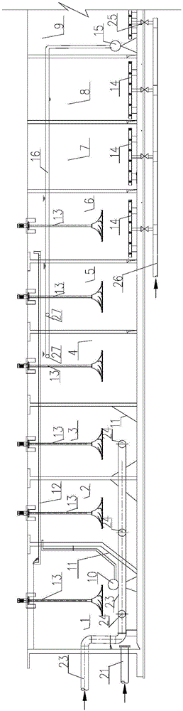
[0044] See figure 1 , a sludge anoxic and enhanced fermentative hydrolysis of multi-format A 2 O system, the sewage enters the system through the water inlet pipe 23, the multi-format A 2 O system includes sludge anoxic grid 1, 1# enhanced fermentation hydrolysis grid 2, 2# enhanced fermentation hydrolysis grid 3, 1# anoxic grid 4, 2# anoxic grid 5, transition grid 6, 1# aerobic grid 7 , 2# aerobic grid 8, 3# aerobic grid 9, and secondary settling tank 22.
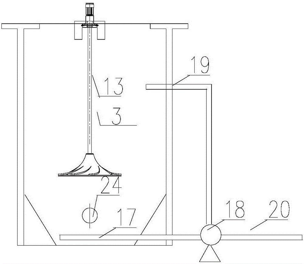
[0045] The sludge anoxic grid 1 and the enhanced fermentation hydrolysis grid, the anoxic grid, the transition grid and the aerobic grid are arranged in sequence, and are separated from each other by a partition wall; the aerobic grid is connected to the secondary settling tank 22 through pipelines; The return sludge pipeline 21 is connected to the sludge anoxic grid 1, and the aerobic grid is connected to the anoxic grid through the internal return pipeline 16 and the internal return sludge pump 15; the supernatant liqu...
Embodiment 2
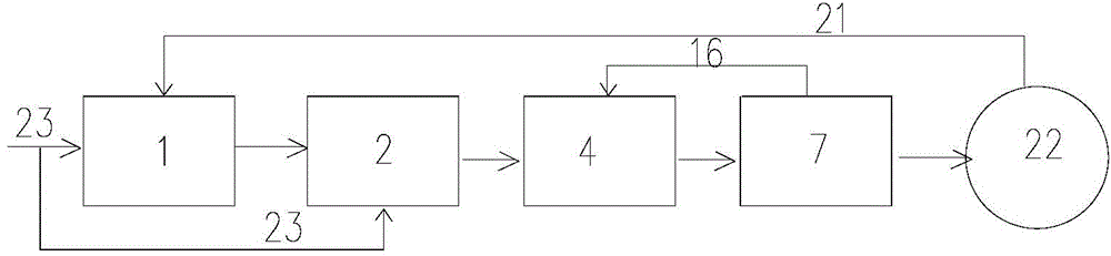
[0052] image 3 It is a flow chart of the system biochemical treatment process proposed by the present invention. image 3 Only 2 (1# enhanced fermentation and hydrolysis grid), 4 (1# anoxic grid), and 7 (1# aerobic grid) are shown in , indicating that the sewage is in the sludge anoxic grid, enhanced fermentation and hydrolysis grid, anoxic grid, Flow between aerobic grids. The method that the system of application embodiment 1 carries out sewage treatment is:
[0053] The sewage enters the system through the water inlet pipe, and all the sewage enters the enhanced fermentation and hydrolysis grid. The hydraulic retention time in the enhanced fermentation and hydrolysis grid is 2 hours, enters the anoxic grid, and then enters the transition grid.
[0054] The last grid of the aerobic grid is equipped with an internal reflux pump to return the mixed solution to the 5 (2# anoxic grid) anoxic grid. There is an internal reflux mixed liquid point 27 in the anoxic grid, and the r...
PUM
 Abstract
Description
Claims
Application Information