Multipoint fastening and reinforcing method for concrete silo structure

A technology for concrete and silos, applied in building construction, building maintenance, construction, etc., can solve the problems of poor overall bearing capacity and rigidity reinforcement effect of silos, poor co-working ability of old and new structures, poor working ability of old and new structures, etc. Achieve the effect of good collaborative work performance, strong engineering application value, and fast construction

Active Publication Date: 2015-06-03
CCCC FOURTH HIGHWAY ENG +1
View PDF6 Cites 6 Cited by
  • Summary
  • Abstract
  • Description
  • Claims
  • Application Information

AI Technical Summary

Problems solved by technology

However, in the technical solution provided by the above method, on the one hand, the external prestressed reinforcement requires the anchorage part of the cylinder wall to have a larger bearing capacity because the anchorage part bears a larger stress; if the concrete silo with a larger diameter is pre-reinforced, the The pretension of the prestressed beam is obviously not desirable; on the other hand, there are defects such as large loss of prestress, large local stress, poor ability to work together between old and new structures, and it is prone to strength or fatigue damage during long-term use
[0008] In short, the traditional reinforcement method is equivalent to "belt" or "plating", which only has the effect of improving the local bearing capacity or durability, and has a poor effect on the overall bearing capacity and stiffness of the silo, especially the joint work of the old and new structures The ability is poor, and the structural force also urgently needs to be improved

Method used


Image

  • Multipoint fastening and reinforcing method for concrete silo structure
  • Multipoint fastening and reinforcing method for concrete silo structure
  • Multipoint fastening and reinforcing method for concrete silo structure

Examples


Embodiment Construction

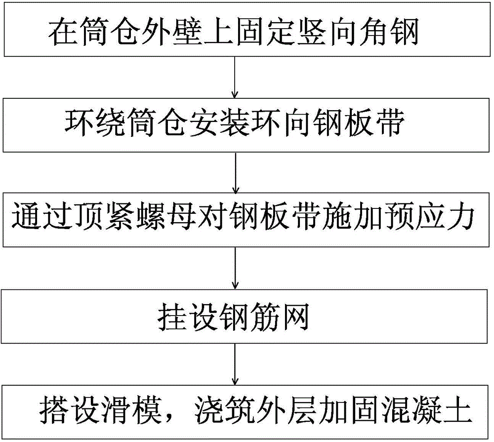
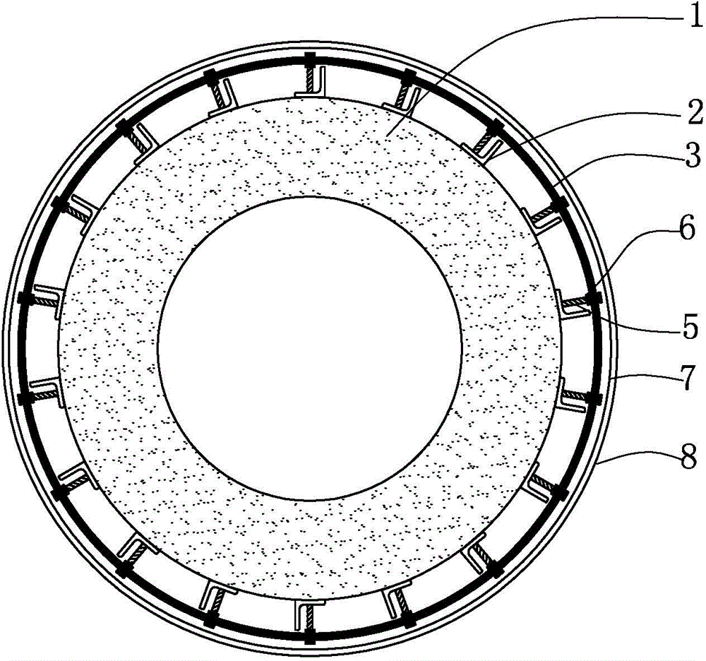
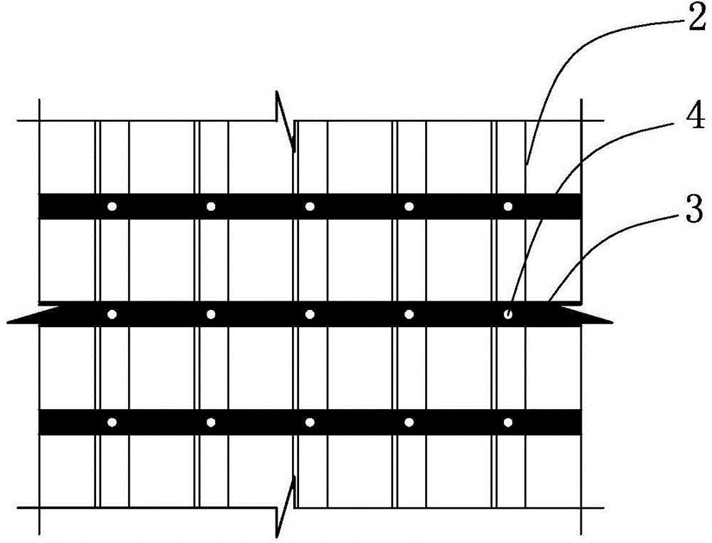
[0029] The multi-point fastening body reinforcement method for concrete silos of the present invention is a reinforcement method for the existing silo structure. Through the evaluation of the bearing capacity of the existing silo structure, this method can be used when the bearing capacity cannot meet the load requirements of the structure. Strengthen the silo structure. The present invention adopts the vertical angle steel backing plate and the hoop prestressed steel strip, and the stress of the hoop prestressed steel strip is the main force, and the vertical angle steel backing plate is supplemented; The original silo wall is combined, and the hoop prestressed steel belt applies the prestress required to increase the bearing capacity through high-strength bolts. After the multi-point fastening system is completed, the silo is hung with steel mesh, concrete is poured and maintained, and the multi-point fastening is completed. reinforcement. The reinforcing method flow proces...


PUM


Abstract

The invention provides a multipoint fastening and reinforcing method for a concrete silo structure. The method comprises the steps: firstly, arranging a vertical unequal-sided angle steel on the external wall of a silo at intervals of certain spacing, and equidistantly planting chemical anchor bolts along the vertical directions of the angle steels so as to anchor the angle steels on the wall of the silo, wherein long sides of the angle steels are tightly attached to the surface of the external wall of the silo; then, arranging a steel plate strip, which horizontally encircles the silo, at intervals of certain spacing along the vertical direction of the silo; forming a bolt hole in each part, directly facing to the corresponding long side of each corresponding angle steel, of each corresponding steel plate strip; enabling bolts to penetrate through the bolt holes in the steel plate strips from outside to inside, and arranging a puller nut at the part, located between the corresponding steel plate strip and the corresponding angle steel, of each bolt; screwing the bolts so as to enable the front ends of the bolts to be abutted against the long sides of the angle steels, and meanwhile, outwards turning the puller nuts so as to enable the puller nuts to be outwardly abutted against the steel plate strips and apply certain prestress to the steel plate strips; then, hanging a reinforcing mesh; finally, building a sliding formwork, and pouring a layer of reinforced concrete outside the wall of the silo.

Description

technical field [0001] The invention relates to a reinforcement method for a concrete silo structure, which belongs to the fields of civil engineering and building reinforcement. Background technique [0002] Concrete silo structures are more and more widely used in grain, building materials, coal, metallurgy, electric power, chemical and other industries, especially in cement production and grain storage enterprises because of their low construction cost and large capacity. However, due to imperfect silo construction specifications and defects in the construction process, many silo structures have potential safety hazards. On the one hand, the defects in the construction process are becoming more and more obvious with the increase of the service life of the concrete silo. On the other hand, with the increase of the service life of the silo structure, the bearing capacity of the silo drops sharply, and some silos are even overloaded. , Seriously affecting the use safety of ...

Claims


Application Information

Patent Timeline
Patent Type & Authority Applications(China)
IPC IPC(8): E04G23/02
Inventor 高晓磊张崇厚阿不力克木卡吾力
Owner CCCC FOURTH HIGHWAY ENG
Why Eureka
Try Eureka