
Temperature control system for ageing cabinet for multiple direct-current power supplies

A technology of temperature control system and DC power supply, applied in the field of power supply, which can solve the problems of poor adaptability of products of various capacity levels, difficult cost-effective energy feedback, energy dispersion, etc., and achieve good temperature control effect, high working reliability and stability , uniform heating effect

Inactive Publication Date: 2015-06-03
XIAN ZHONGKEMAITE ELECTRONICS TECH EQUIP
View PDF0 Cites 6 Cited by
  • Summary
  • Abstract
  • Description
  • Claims
  • Application Information

AI Technical Summary

Problems solved by technology

China is the world's largest manufacturer of small and medium power power supply products. Traditional aging test methods cause huge waste of energy and poor adaptability to products of various capacity levels. Therefore, research on more economical and adaptable energy-saving aging test systems is of great importance. very important
[0003] However, there are still a lot of problems in the aging of small and medium power DC power supplies. Among them, the aging energy of small and medium power DC power supplies is scattered, and it is difficult to achieve cost-effective energy feedback. Traditional aging cabinets use resistors as loads, which generate a lot of heat consumption during the aging process, resulting in energy waste. , and need timely heat dissipation

Method used


Image

  • Temperature control system for ageing cabinet for multiple direct-current power supplies
  • Temperature control system for ageing cabinet for multiple direct-current power supplies

Examples


Embodiment Construction

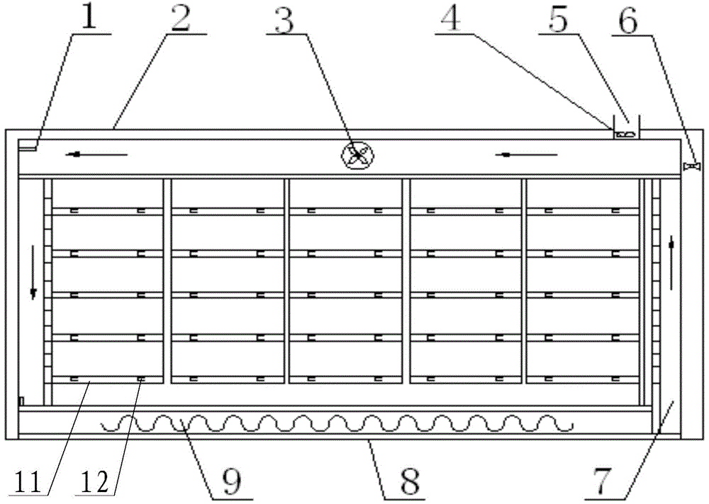
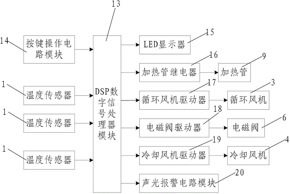
[0026] Such as figure 1 and figure 2 As shown, in the temperature control system for multiple DC power aging cabinets described in the present invention, the multiple DC power aging cabinets include an aging cabinet body 2 with a hollow base 8, and the base 8 is provided with a The heating pipe 9 for heating the aging cabinet body 2, the interior of the aging cabinet body 2 is provided with a multi-layer aging rack 11, and a plurality of aging racks 11 for plugging in multiple DC power supplies are provided on each layer. A power socket 12, a plurality of the power sockets 12 are first connected in series to form a plurality of series branches, and then a plurality of series branches are connected in parallel. The side and top of the aging frame 11 are provided with interconnected circulating air ducts 7, which are located in the A circulating fan 3 is arranged in the circulating air duct 7 on the top of the aging frame 11, and a cooling air duct 5 is arranged on the periphe...


PUM


Abstract

The invention discloses a temperature control system for an ageing cabinet for multiple direct-current power supplies. The ageing cabinet for the multiple direct-current power supplies comprises an ageing cabinet body with a base, wherein a heating tube is arranged in the base; a multi-layer ageing rack is arranged in the ageing cabinet body; a plurality of power supply sockets are arranged on each layer of ageing racks; circulating air flues are arranged on the side surface and the top of each aging rack; circulating air blowers are arranged in the circulating air flues; cooling air flues are arranged at the peripheries of the circulating air flues; solenoid valves and cooling fans are arranged in the cooling air flues; the temperature control system comprises a DSP (digital signal processor) module, an input end of the DSP (digital signal processor) module is connected with a button operation circuit module and a plurality of temperature sensors; an output end of the DSP (digital signal processor) module is connected with an LED (light-emitting diode) display, a heating tube relay, a circulating fan driver, a solenoid valve driver, a cooling fan driver and a sound-light alarm circuit module. The temperature control system can be used for regulating the temperature in the cabinet body of the aging cabinet in real time, and is high in working reliability and stability.

Description

technical field [0001] The invention relates to the field of power supply technology, in particular to a temperature control system for multiple DC power aging cabinets. Background technique [0002] As a power supply device for electronic equipment, DC power supply has been widely used in computer, communication, railway, aerospace, household appliances and other fields. In order to improve the stability and reliability of power supply products, manufacturers at home and abroad generally adopt the resistance energy consumption method to carry out aging tests on small and medium power supplies. China is the world's largest manufacturer of small and medium power power supply products. Traditional aging test methods cause huge waste of energy and poor adaptability to products of various capacity levels. Therefore, research on more economical and adaptable energy-saving aging test systems is of great importance. Very important. [0003] However, there are still a lot of probl...

Claims


Application Information

Patent Timeline
IPC IPC(8): G05D23/30G01R31/40
Inventor 梁保华
Owner XIAN ZHONGKEMAITE ELECTRONICS TECH EQUIP
Learn More