Waveguide device microwave gas discharge numerical simulation method

A waveguide device and gas discharge technology, applied in electrical digital data processing, instruments, special data processing applications, etc., can solve the problems of complex object structure, long calculation time, low accuracy, etc., to achieve protection simulation and prenatal Design, shorten the design cycle, reduce the effect of computing cost

Active Publication Date: 2015-06-03
NANJING UNIV OF SCI & TECH
View PDF2 Cites 8 Cited by
  • Summary
  • Abstract
  • Description
  • Claims
  • Application Information

AI Technical Summary

Problems solved by technology

Compared with the long period and high cost of the experimental method, the prediction by the numerical method faces difficulties such as complex structure of the solution object, high nonlinearity, long calculation time and low calculation accuracy.
[0003] At present, the analysis method of microwave breakdown and gas discharge mainly adopts the time-domain finite difference method in the differential equation method, such as literature 1.Yee, Jick H., et al, "Propagation of intense microwave pulses in air and in a waveguide , "IEEE Transactions on Antennas and Propagation, 39.9 (1991), pp:1421-1427. and finite volume integration method, such as literature 2.Adnane Hamiaz, et al," Finite Volume Time Domain modeling of microwave breakdown and plasma formation in a metallic aperture, "Computer Physics Communications 183(2012), pp:1634–1640. The above-mentioned published documents are all used to analyze the two-dimensional gas discharge problem with simple structure, although the numerical distribution and Prediction, but there are disadvantages such as simple model, low accuracy, and long calculation time
At present, there are no literature reports on the simulation of gas discharge phenomena in waveguide structures using the time-domain spectral element method

Method used


Image

  • Waveguide device microwave gas discharge numerical simulation method
  • Waveguide device microwave gas discharge numerical simulation method
  • Waveguide device microwave gas discharge numerical simulation method

Examples


Embodiment Construction

[0020] The present invention will be described in further detail below in conjunction with the accompanying drawings.

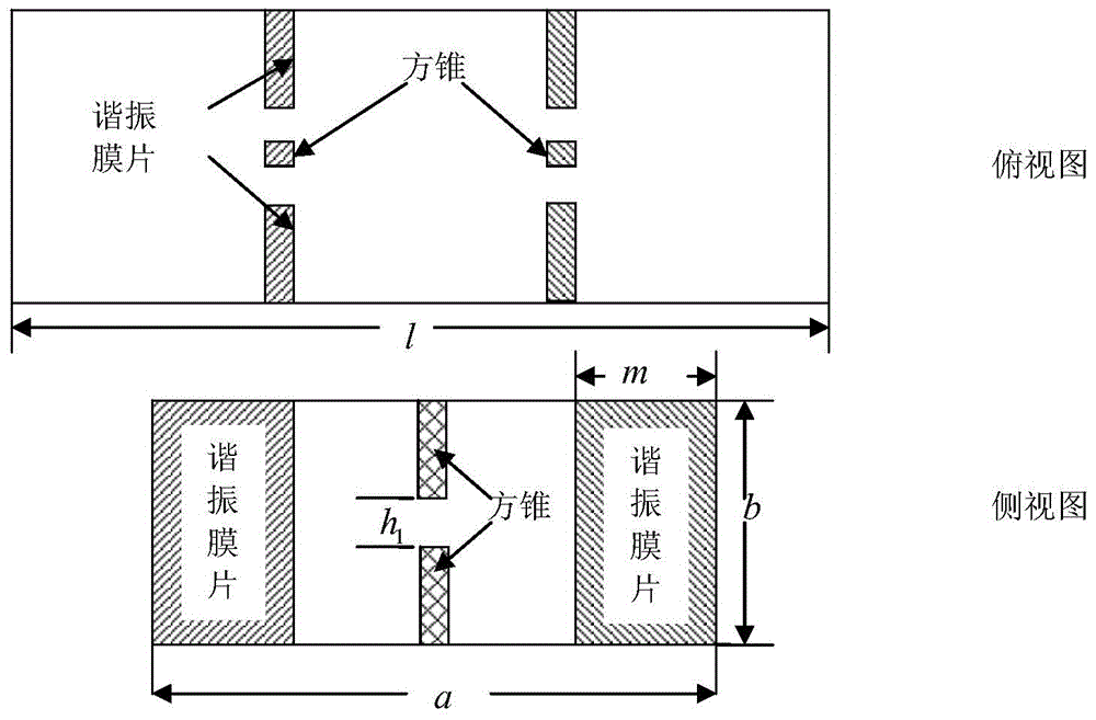
[0021] The invention provides a numerical simulation method for microwave gas discharge of a waveguide device. Combined with the accompanying drawings below, with figure 1 The shown device with a waveguide structure with a slot is taken as an example, and the specific steps of the present invention are further described in detail.

[0022] see figure 1 The cross-sectional schematic diagram of the waveguide structure with slots is shown, and the geometric dimensions of the model are as follows: BJ-100 waveguide model is used, the interior is filled with argon, the pressure is 3.9Torr, the long side of the waveguide a=22.86mm, the short side of the waveguide b=10.16mm, and the total length of the waveguide is l =27.45mm, the center distance of the resonant element is 9.15mm, the discharge electrode is a pair of rectangular parallelepipeds, the side length a1=...


PUM


Abstract

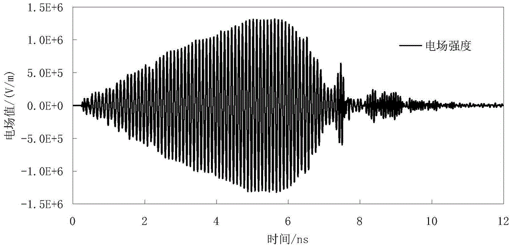
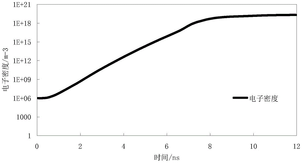
The invention discloses a waveguide device microwave gas discharge numerical simulation method. According to the method, a microwave gas discharge fluid model in a waveguide structure is built, accurate numerical analysis is performed on electron density, electron fluid velocity and average electron energy during gas breakdown, and accordingly, the law of changing of the electric field intensity and the electron density at different observation positions along with the time in the condition of gas discharge of waveguide devices in different geometric profile complicated structures. The modeling of waveguide devices in any complicated structures can be achieved based on the time domain spectral element method; the generated mass matrix is a block diagonal matrix, and an inverse matrix can be obtained directly, so that the calculation time is reduced greatly; meanwhile, by the aid of the numerical simulation method, the breakdown threshold obtained through electric field distribution and electron density inside the waveguide devices through repeated experiments can be prevented, and accordingly, the design period is shortened, the design cost is saved, and the method is quite applicable to effective simulation design and numerical simulation of waveguide devices with discontinuous structures.

Description

technical field [0001] The invention belongs to the simulation technology of electromagnetic characteristics involving multiple physical fields, in particular to a novel numerical simulation method for analyzing gas discharge breakdown of waveguide structure microwave devices. Background technique [0002] With the rapid development of space technology, the circuit integration of electronic equipment is getting higher and higher, and the operating frequency of microwave devices is constantly increasing; at the same time, with the continuous maturity of high-power pulse generator technology, its output power can reach the order of tens of Gw. The numerical analysis and computer simulation of the microwave breakdown and gas discharge phenomena of microwave devices with different gas-filled space waveguide structures are increasingly valued by scientific research institutions, and it is one of the hot problems in the field of space technology and high-power pulses. The research...

Claims


Application Information

Patent Timeline
Patent Type & Authority Applications(China)
IPC IPC(8): G06F17/50
Inventor 陈如山丁大志樊振宏盛亦军钱程
Owner NANJING UNIV OF SCI & TECH
Why Eureka
Try Eureka