Integrated multipath dielectric phase shifter

A phase shifter and medium technology, applied in circuits, waveguide-type devices, electrical components, etc., can solve the difficulty and poor consistency of the assembly of the base station electrical adjustment antenna, the disadvantage of the overall layout of the antenna feed network, and the zero phase shifter. Too many components, etc., to achieve the effect of convenient feeding network design, simple manufacturing and assembly, and reduced size

Inactive Publication Date: 2015-06-03
WUHAN HONGXIN TELECOMM TECH CO LTD
View PDF6 Cites 13 Cited by
  • Summary
  • Abstract
  • Description
  • Claims
  • Application Information

AI Technical Summary

Problems solved by technology

[0004] 1. When the multi-channel phase shifter composed of this type of phase shifter unit is used for the electric adjustment antenna of the base station in a multi-unit array, the length of the phase shifter is long and the occupied area is too large, which is very unfavorable for the antenna feed network. overall arrangement
[0005] 2. There are too many components of the phase shifter, and the assembly is complicated, which leads to the difficulty and consistency of the assembly of the base station electronically adjustable antenna, and the manufacturing cost is relatively high.

Method used


Image

  • Integrated multipath dielectric phase shifter
  • Integrated multipath dielectric phase shifter
  • Integrated multipath dielectric phase shifter

Examples


Embodiment Construction

[0033] The technical solutions of the present invention will be described in detail below in conjunction with the accompanying drawings and embodiments.

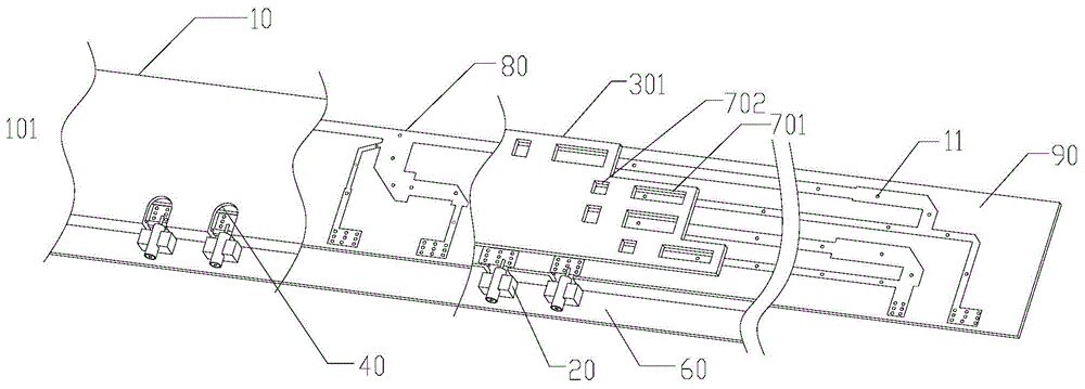
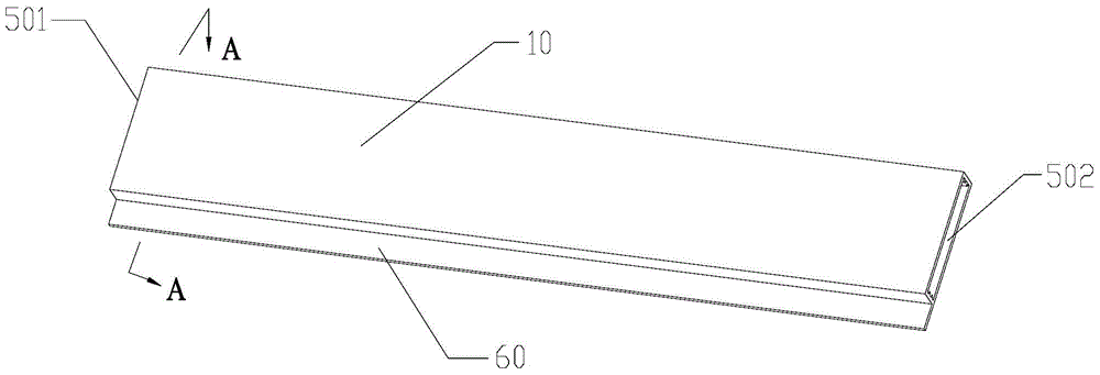
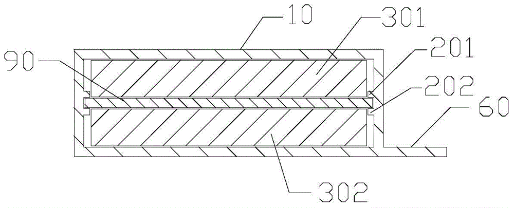
[0034] see figure 1 The multi-channel integrated dielectric phase shifter 101 provided in Embodiment 1 of the present invention includes a cavity 10, a first dielectric board 301, a second dielectric board 302 and a PCB board 90:

[0035] The cavity 10 is integrally formed in the shape of a cuboid, with openings 501 and 502 at both ends, and guide rail grooves on the side walls. The PCB board 90 is fixed in the cavity 10 through the guide rail grooves. Let the length, width and height of the cavity 10 be A, B, and C respectively, A is greater than B, and the two ends with a length of B have openings 501 and 502 respectively, so that when using the multi-channel integrated dielectric phase shifter provided by the present invention, The first dielectric plate 301 and the second dielectric plate 302 are connected to the slidi...


PUM


Abstract

The invention provides an integrated multipath dielectric phase shifter. The integrated multipath dielectric phase shifter comprises a cavity (10), a first dielectric plate (301), a second dielectric plate (302) and a PCB (90), wherein holes are formed in the two ends of the cavity (10); guide rail grooves are respectively formed in the two side walls of the cavity (10); the PCB (90) is fixedly arranged in the cavity (10) through the guide rail grooves; feeder lines (80) are symmetrically attached to the upper surface and the lower surface of the PCB (90); metallized via holes (11) are formed inside the PCB (90); the first dielectric plate (301) and the second dielectric plate (302) are symmetrically arranged, respectively cover the upper surface and the lower surface of the PCB (90) and slides in the longer side wall direction of the cavity; through holes corresponding to the feeder lines (80) are formed in the first dielectric plate (301) and the second dielectric plate (302). The phase shifter disclosed by the invention is low in profile, small in size, less in parts and high in erecting welding consistency.

Description

technical field [0001] The invention relates to the field of mobile communication base station antennas, in particular to a dielectric phase shifter for changing the phase of a transmission signal. Background technique [0002] The phase shifter is the core component of the electronically adjustable antenna. The development of mobile communication base station antennas has put forward higher requirements for phase shifters, such as smaller volume, wider operating frequency band, better intermodulation performance and easier processing technology. In the prior art, the dielectric phase shifter changes the propagation rate of the signal by moving the medium in the phase shifter, thereby realizing phase shifting. [0003] But, the medium phase shifter of prior art, for example the medium phase shifter of patent No. CN102544733B, see Figure 9 , including a power splitter group, a transmission line and several dielectric phase shifters, the power splitter group includes a maste...

Claims


Application Information

Patent Timeline
IPC IPC(8): H01P1/18H01Q3/32
Inventor 汪振宇丁勇赖青松郑志清
Owner WUHAN HONGXIN TELECOMM TECH CO LTD
Why Eureka
Try Eureka