Optical communication lens, optical communication module, and molding die

A technology for forming molds and optical communication, which is applied in the direction of condensers, household appliances, and other household appliances. It can solve the problems of high cost and expensive glass lenses, and achieve the effects of improved mold release, high optical performance, and uniform shrinkage.

Inactive Publication Date: 2015-06-03
KONICA MINOLTA INC
View PDF6 Cites 2 Cited by
  • Summary
  • Abstract
  • Description
  • Claims
  • Application Information

AI Technical Summary

Problems solved by technology

However, glass lenses with an aspheric surface are generally expensive, and there is a problem that the cos

Method used


Image

  • Optical communication lens, optical communication module, and molding die
  • Optical communication lens, optical communication module, and molding die
  • Optical communication lens, optical communication module, and molding die

Examples


Example

[0066] (First embodiment)

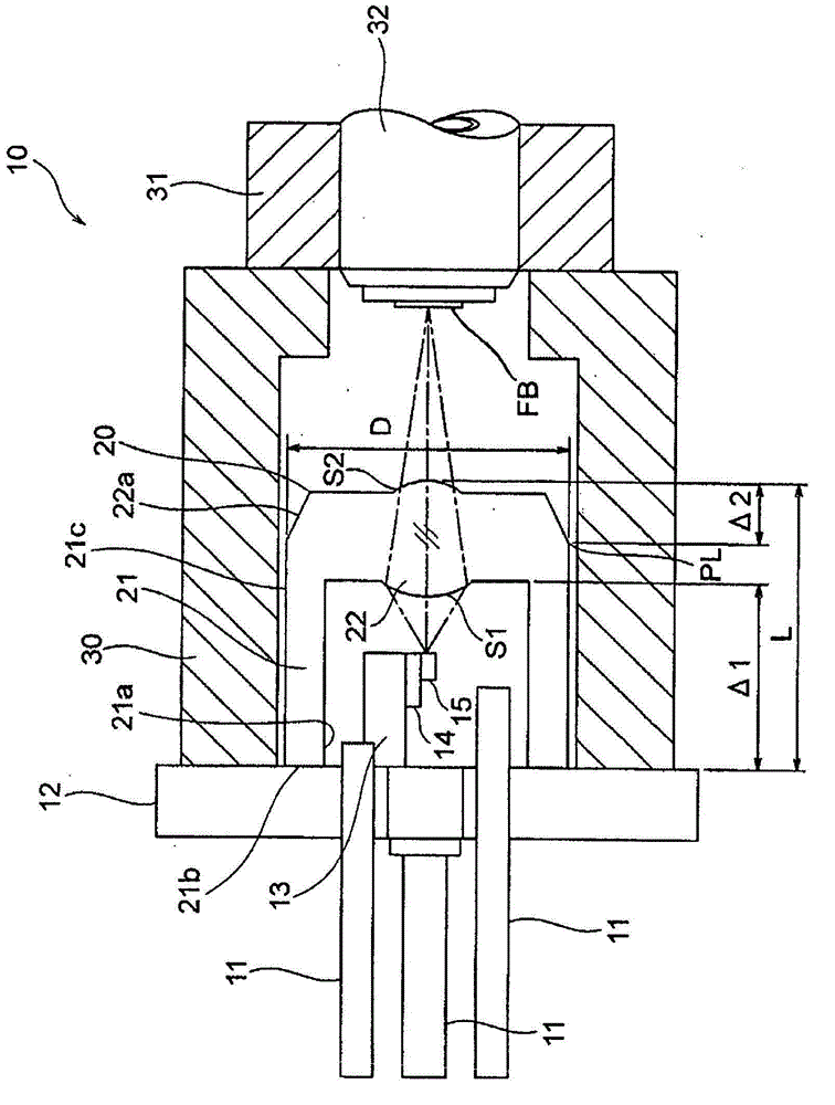
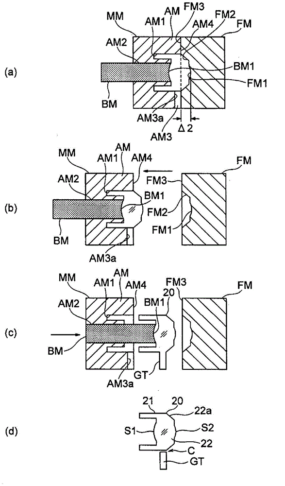
[0067] figure 2 It is a figure which shows the manufacturing process (a)-(d) of the lens suitable for the above-mentioned embodiment. The fixed mold FM has a transfer surface FM1 that transfers the optical surface S2, a transfer surface (taper surface slope) FM2 that transfers the tapered surface 22a, and a mating surface FM3. The mating surface FM3 of the fixed mold FM is located at a position away from the innermost (here, the center of the transfer surface FM1) of the fixed mold FM in the optical axis direction by Δ2=L / 10 to L / 2. The transfer surface FM2 is made a rough surface.

[0068] On the other hand, the movable mold MM that is movable with respect to the fixed mold FM has a main mold AM and an insert mold (sub-mold) BM. The main mold AM has a transfer surface AM1 of the transfer leg 21, a circular opening AM2 in the center, an inject part AM3 for injecting resin from the outside, and a mating surface AM4.

[0069] The cylindrical insert mold ...

Example

[0074] (Second embodiment)

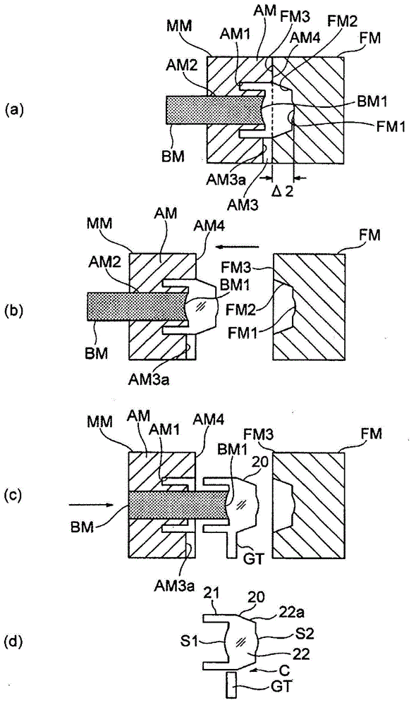
[0075] image 3 It is a figure which shows the manufacturing process (a)-(d) of the lens of 2nd Embodiment. In this embodiment, the distance Δ2 in the optical axis direction from the innermost surface of the fixed mold FM to the mating surface FM3 of the fixed mold FM is further increased compared to the first embodiment. Since the other configuration is the same as the above-mentioned embodiment, the description is omitted.

[0076] (3rd embodiment)

[0077] Figure 4 It is a figure which shows the manufacturing process (a)-(d) of the lens of 3rd Embodiment. This embodiment is different from the first embodiment in that a transfer surface (curved surface transfer surface) FM2' for transferring a curved surface is provided around the transfer surface FM1 of the fixed mold FM. Thus, as Figure 4 As shown in (d), around the optical surface S2 of the lens 20, a curved surface 22a' whose diameter decreases as it approaches the optical surface S2 is formed....

Example

[0078] (Fourth embodiment)

[0079] Figure 5 It is a figure (a)-(d) which shows the manufacturing process of the lens of 4th Embodiment. In the present embodiment, it is an example in which the diameter around the transfer surface FM1 of the fixed mold FM is reduced compared to the first embodiment. Thus, as Figure 5 As shown in (d), a stepped surface 22a" having a reduced diameter is formed around the optical surface S2 of the lens 20. Here, FM2 is a stepped transfer surface. It is preferable to use the stepped surface 22a" as the outer peripheral surface of the flange portion. (The outer peripheral surface) is made into a rough surface. Since the other configuration is the same as the above-mentioned embodiment, the description is omitted.

[0080] (Fifth embodiment)

[0081] Image 6 It is a figure (a)-(d) which shows the manufacturing process of the lens of 5th Embodiment. In this embodiment, with respect to the fourth embodiment, the diameter around the transfer surface FM...


PUM


Abstract

Provided are: an optical communication lens which exhibits improved formability, is capable of suppressing contamination and the like during the production step, and reduces costs; an optical communication module using the same; and a molding die. After the material cools, a movable mold (MM) is displaced so as to integrally move away from a fixed mold (FM). During this displacement, the contact surface (FM3) of the fixed mold (FM) is positioned at Δ2=L/10 to L/2 in the optical axis direction from the innermost point of the fixed mold (FM); hence, the molded product is stuck to the movable-mold (MM) side. Also, even if for example a burr is formed along the parting line, there is little risk that the broken burr would adhere to the optical surface of the lens. Furthermore, the contact surface (FM3) of the fixed mold (FM) is positioned at Δ2=L/10 to L/2 in the optical axis direction from the innermost point of the fixed mold (FM); hence, it is possible to separate the gate (GT) from the optical surface (S2), and when cutting the gate and performing the polishing treatment, the adhesion of plastic bits and polished material to the optical surface (S2) is suppressed.

Description

Technical field [0001] The present invention relates to a lens for optical communication that couples light from an optical element such as a semiconductor laser to an optical fiber or a light-receiving element used in optical communication, etc., an optical communication module, and a molding die suitable for the production of such a lens. Background technique [0002] In optical communication and the like, in order to perform optical coupling between a semiconductor laser or a light receiving element and an optical fiber with good efficiency, a lens for optical coupling is used. However, in conventional optical coupling lenses, a structure in which a glass lens is supported mainly by stainless steel legs is widely used. However, glass lenses with aspheric surfaces are generally expensive, and because they have to go through a process of assembling the feet different from the raw materials, there is a problem of significant high cost. Therefore, as shown in Patent Document 1, a...

Claims


Application Information

Patent Timeline
IPC IPC(8): G02B6/42B29C45/00B29C33/00H01L31/0232H01S5/022G02B7/02
CPCB29C33/005B29C45/0025G02B6/4206G02B7/022G02B19/0014G02B19/0052H01L31/02325G02B6/4292G02B6/4255B29C2045/0034B29L2011/0016H01S5/02212H01S5/02253
Inventor 中山佳佑
Owner KONICA MINOLTA INC
Why Eureka
Try Eureka