Miniature antenna unit capable of controlling wave beam widths and large-scale antenna array capable of controlling wave beam widths

A large-scale antenna and beamwidth technology, applied in antenna arrays, antennas, slot antennas, etc., can solve problems such as narrow beamwidth, achieve the effect of reducing size, small wind receiving area, and controlling beamwidth

Inactive Publication Date: 2015-06-10
庄昆杰
View PDF8 Cites 6 Cited by
  • Summary
  • Abstract
  • Description
  • Claims
  • Application Information

AI Technical Summary

Problems solved by technology

In addition, the beam width of ordinary antennas is generally around 65°±10°, and the beam width is relatively narrow

Method used


Image

  • Miniature antenna unit capable of controlling wave beam widths and large-scale antenna array capable of controlling wave beam widths
  • Miniature antenna unit capable of controlling wave beam widths and large-scale antenna array capable of controlling wave beam widths
  • Miniature antenna unit capable of controlling wave beam widths and large-scale antenna array capable of controlling wave beam widths

Examples


Embodiment Construction

[0023] The specific embodiments of the present invention will be described in detail below in conjunction with the accompanying drawings, but it should be understood that the protection scope of the present invention is not limited by the specific embodiments.

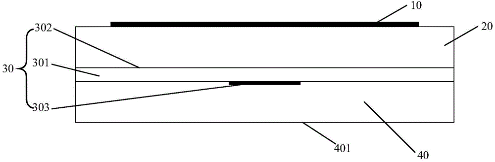
[0024] According to an embodiment of the present invention, a miniaturized antenna unit with a controlled beam width is provided, figure 2 It is a structural diagram of the miniaturized antenna unit, including: a radiation sheet 10 , a dielectric layer 20 , a microstrip slot antenna substrate 30 and a reflection cavity 40 .

[0025] Among them, such as figure 2 As shown, the dielectric layer 20 is arranged between the radiation sheet 10 and the front of the microstrip slot antenna substrate 30, and the dielectric constant of the dielectric layer 20 is greater than that of air; the microstrip slot antenna substrate 30 adopts a high dielectric constant substrate sheet 301, and the dielectric constant of the high diele...


PUM


Abstract

The invention discloses a miniature antenna unit capable of controlling wave beam widths and a large-scale antenna array capable of controlling wave beam widths. The miniature antenna unit comprises a radiation plate, a dielectric layer, a micro-strip slot antenna substrate and a reflecting cavity; the dielectric layer is arranged between the radiation plate and the front surface of the micro-strip slot antenna substrate; the dielectric constant of the dielectric layer is greater than that of air; the micro-strip slot antenna substrate is a high-dielectric-constant substrate; and the dielectric constant of the high-dielectric-constant substrate is greater than 3.5; and the reflecting cavity is formed in the reverse surface of the micro-strip slot antenna substrate. The miniature antenna unit and the large-scale antenna array are small in size, and the wave beam widths can be controlled by changing the dielectric constant of the dielectric layer in the antenna unit and the dielectric constant of the high-dielectric-constant substrate.

Description

technical field [0001] The invention relates to the technical field of mobile communication, in particular to a miniaturized antenna unit and a large-scale antenna array with controllable beam width. Background technique [0002] With the rise of smart terminals and the enrichment of wireless data application services, the number of data users in wireless communication systems has increased significantly, and data content is no longer limited to traditional text or images. The increasing demand for wireless network traffic has led to explosive growth. According to the forecast of market institutions, wireless data services will increase by 500-1000 times in the next ten years, with an average annual growth rate of 1.6-2 times, which puts forward higher requirements on the network capacity of wireless communication systems. There are many ways to improve the network capacity of wireless communication systems, mainly including improving spectrum efficiency, increasing network...

Claims


Application Information

Patent Timeline
IPC IPC(8): H01Q1/38H01Q13/08H01Q13/10H01Q21/00
CPCH01Q1/38
Inventor 庄昆杰
Owner 庄昆杰
Why Eureka
Try Eureka