High-speed large-view-field multi-spectral photoacoustic imaging method and device

A photoacoustic imaging and multi-spectral technology, which is applied in the direction of measuring devices, using spectral diagnosis, color/spectral characteristic measurement, etc., can solve the difficulty of system development that increases the consumption of scanning time, the impact of slow mechanical scanning, and the difficulty in obtaining scanning speed etc. to overcome the problem of small field of view, easy to operate, and avoid imaging delay

Active Publication Date: 2015-06-17
FUJIAN UNIV OF TECH
View PDF8 Cites 15 Cited by
  • Summary
  • Abstract
  • Description
  • Claims
  • Application Information

AI Technical Summary

Problems solved by technology

2. Two-dimensional galvanometer scanning, this type of scanning method is commonly used in photoacoustic microscopy imaging systems, and its imaging speed has been greatly improved, but it is difficult to obtain large-area two-dimensional scanning images in a short time due to the limitation of the field of view , and the two-dimensional galvanometer scanning control requires the cooperation of two dimensions, which also increases the consumption of scanning time and the difficulty of system development
This type of method must be affected by the small field of view in one direction and also by the slow speed of mechanical scanning, making it difficult to obtain faster scanning speeds
In addition, there are limited-angle data acquisition, electronic scanning, etc., but these methods are still difficult to break through the limitations of algorithms and field of view to obtain higher imaging speed and larger field of view space

Method used


Image

  • High-speed large-view-field multi-spectral photoacoustic imaging method and device
  • High-speed large-view-field multi-spectral photoacoustic imaging method and device
  • High-speed large-view-field multi-spectral photoacoustic imaging method and device

Examples


Embodiment Construction

[0031] The present invention will be further described in detail below in conjunction with the embodiments:

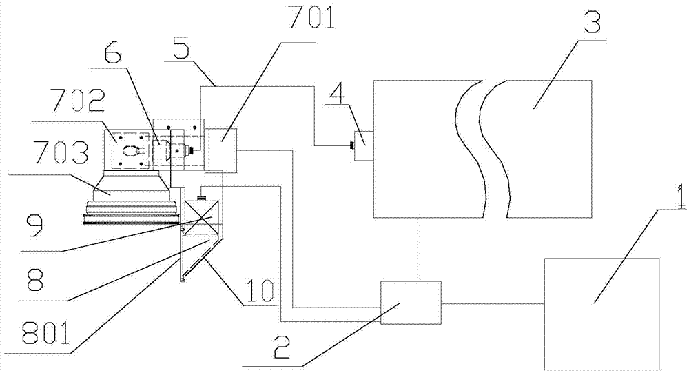
[0032] by figure 1 It can be seen that a high-speed large-field multi-spectral photoacoustic imaging device of the present invention includes a photoacoustic excitation light source generating component, an ultrasonic coupling component, a photoacoustic signal collection, and a device scanning synchronization control component; the photoacoustic excitation light source generating component includes a pulse laser 3, Laser coupler 4, optical fiber 5, laser collimating beam expander 6, mirror 702, one-dimensional scanning galvanometer 701, F-theta lens group 703, the pulse laser 3, laser coupler 4, optical fiber 5, laser collimator The straight beam expander 6, the mirror 702, the one-dimensional scanning galvanometer 701, and the F-theta lens group 703 are connected in sequence; the ultrasonic coupling component includes a water tank 8, an ultrasonic coupling liquid, an acou...


PUM

PropertyMeasurementUnit
lengthaaaaaaaaaa

Abstract

The invention discloses a high-speed large-view-field multi-spectral photoacoustic scanning imaging method and device. According to the scanning imaging method, a one-dimension scanning galvanometer and an F-theta lens set are utilized for gathering the collimated pulse laser into linear light spots to activate an organized body to generate light-induced ultrasonic signals, and after a sound reflector arranged in the lateral direction reflects photoacoustic signals, a non-focus ultrasonic transducer is used for receiving externally transmitted ultrasonic signals. According to the system, only a one-dimension scanner is needed for scanning, an algorithm is not needed, and a two-dimension photoacoustic absorbing distribution graph can be obtained at a high speed. The scanning imaging device comprises a photoacoustic light source generating activating module, an ultrasonic coupling module and a photoacoustic signal collecting and device scanning synchronous control module. According to the scanning imaging method, only a one-dimension optical scanning mode is adopted, the difficulty of scanning control is lowered, the imaging time is shortened, and large-view-field and high-definition two-dimension tomography is achieved. The scanning imaging device is simple, low in cost, portable, easy to popularize and capable of performing clinical monitoring.

Description

Technical field [0001] The invention belongs to scanning tomography imaging technology, and particularly relates to a high-speed multi-spectrum large-field-of-view photoacoustic scanning imaging method and device. Background technique [0002] F-theta lens is a lens system with special requirements in laser scanning imaging system. It can focus the laser beam reflected by a scanning element such as a laser galvanometer on the scanning plane to obtain a one-dimensional or two-dimensional scanning image. It has the characteristics of large field of view, small relative aperture, uniform illuminance, and flat image surface, and is widely used in laser marking, cutting, perforation, and stripe code recognition. Because it is easy to combine with various scanning devices, it has the characteristics of high response speed, large field of view, focusing spot can be changed according to requirements, and strong environmental adaptability, which has broad application prospects. [0003] P...

Claims


Application Information

Patent Timeline
Patent Type & Authority Applications(China)
IPC IPC(8): A61B5/00G01N21/17G01N21/25
CPCA61B5/0075A61B5/0095G01N21/1702G01N21/25
Inventor 谢文明郑少锋黄诗浩林抒毅邵明聂明星蒋新华蔡思静
Owner FUJIAN UNIV OF TECH
Why Eureka
Try Eureka